COMPONENTS PARTS OF A THEODOLITE:
Leveling head: It supports the main working parts of the instrument and screw on
the tripod.
The head comprises of two parts:
• Leveling base or tribrach fitted with leveling foot screws for leveling the
instrument.
• Movable head or centering arrangement for centering the vertical axis
accurately over the station.
Lower circular horizontal metal plate:
It carries a circular graduated arc. It is
silvered and graduated from 00 to 3600 in a clock wise direction.
Upper circular horizontal metal plate: The upper plate carries an index and
vernier to Read fine reading on the graduated horizontal circle.
Telescope: Fitted to a horizontal axis, it consists of eye piece and diaphragm at
one end and objective glass at the other end.
The telescope has focusing screw by
which any Object can be bisected.
Circular graduated arc on a vertical circle: It is attached to the horizontal axis of
the telescope. It is usually divided into 4 quadrants, but in some instruments it is
graduated from 00 to 3600 the sub divisions of the vertical circle are similar to
those of horizontal circle.
Vernier frame: carrying an index and verniers to measure vertical angles.
Lower clamp and lower tangent screw: A lower clamp, clamps the lower plate
and the lower tangent screw enables finely controlled circular motion of lower
plate.
Upper clamp and upper tangent screw: An upper clamp, clamps the upper plate
to lower one, and the upper tangent screw enables finely controlled circular
motion about vertical axis.
Vertical circle clamp and tangent screw: A vertical circle clamp, clamps the
vertical circle and its tangent screw enables a finely controlled circular movement
to be given to the combined telescope and vertical circle about the horizontal
axis.
Circular level: It is located on the top of tribrach.
Plate level: It consist of plate bubble, which keeps the instrument parallel to
horizontal axis.
Compass: A circular or trough compass may be mounted on the vernier plate
between the standards for observing bearings.
Tripod: Theodolite is mounted and fixed on the tripod for each set up. As tripod
has adjustable legs, theodolite can roughly leveled with the adjusting the legs of
tripod.
Land Survey, Setting-Out Engineering, GIS Processing, Structural/Civil Works and General Contracts Call +2347064649087 www.heroizutechng.blogspot.com.ng
Thursday, 15 September 2016
LESSON NOTE ON TEMPORARY ADJUSTMENT OF THEODOLITE Part C
TEMPORARY
ADJUSTMENT OF THEODOLITE

Temporary adjustment are the adjustment which are required to be made at
each setting of the instrument before taking observation. These adjustments are
also known as station adjustments.
The following
three adjustments are required:
1. Setting up
and centring,
2.Levlling
3.Elimination of
parallax.
Setting up and Centring
This involves setting the theodolite exactly over
the station mark or on the station peg. It is done by the following steps:
- The plumb bob is suspended from a small hook attached to the vertical axis of the theodolite
- The instrument is placed over the station mark with the telescope at a convenient height and with the tripod legs set well apart.
- Two legs of the tripod are set frimly into the ground and the third leg is moved radially to bring plumb bob exactly over the station mark. Then the third leg is also pushed into the ground.
- The instrument is roughly centered over the station mark and then by means of the shifting head, the plumb bob is brought excatly over the station mark.
Levelling
The procedure of levelling with three foot
screws is as follows:-
- Turn the upper plate untill the longitudinal axis of the plate level is roughly parallel to a line joining any two of the levelling screws.
- Hold these two levelling screws between the thumb and the first finger and turn them uniformly so that the thumbs move either towards each other or away from each other until the bubble is central.
- Turn the upper palte 90, i.e untill the axis of the level passes over the position of the third levelling screw C.
- Turn this levelling screw C untill the bubble is central.
- Return the upper plate through 90 to its original position. Rotate screws A and B inwards or outwards till the bubble is central.
- Repeat the above steps,till the bubble is central in both the positions.
Elimination of parallax
It consists of
focusing of eyepiece and the objective.
Focussing
the eyepiece This
operation is done to make the cross-hairs appear clearly visible.
The following
steps are involved:-
1.
The
telescope is directed towards the sky or a sheet of white paper held in front
of the objective.
2.
The
eyepiece is moved in or out until the cross-hairs appears clear and distinct.
Focussing
the objective This
operation is done to bring the image of the object in the plane of the
cross-hairs. The following steps are involved:-
1. The telescope is directed towards the object.
2. The focusing screw is turned until the image appear
clear and sharp.
Wednesday, 14 September 2016
Lesson Note On Digital Theodolite
Digital Theodolite
The term digital theodolite can be used to
describe those survey instruments designed to precisely measure horizontal and
vertical angles. In addition to measuring horizontal and vertical angles,
digital theodolite are used to establish straight lines, to establish
horizontal and vertical distances through the use of stadia, and to establish
elevations when used as a level.
A digital theodolite is a survey instrument
using a three-screw leveling base, glass horizontal and vertical circles read
directly with a digital display, and equipped with right-angle optical plummet
for setting over specific points.
The digital theodolite consists of three main
assemblies. The upper assembly, called the alidade, includes the
standards, telescope, digital display for reading the horizontal and vertical
circle, plate bubbles, compass, and upper tangent (slow motion) screw.
The spindle of the alidade on the digital
theodolite fits down into the hollow spindle of the next assembly, the circle
assembly. The circle assembly includes the horizontal circle that is
covered by the alidade plate , the upper clamp screw, and the hollow spindle
previously mentioned.
The hollow spindle of the circle assembly on
the digital theodolite fits down into the leveling head, the final assembly of
the digital theodolite. The leveling head on the digital theodolite
includes the four leveling screws, the half-ball joint about which opposing
screws are manipulated to level the digital theodolite instrument, a threaded
collar that permits attachment of the digital theodolite to a tripod, the lower
clamp and slow-motion screw.
All our digital theodolite carry a minimum of
a 1 year warranty and can be repaired in-house and parts are available on all
models that we sell.
How to
Use a Digital Theodolite Step-by-step
1. Set up
your digital theodolite over a point using the optical plummet device on the
bottom of the digital theodolite.
2. Back
sight your digital theodolite survey instrument by sighting the crosshairs and
focusing telescope and on a reference point. The reference point can be
occupied by a pole at least 150 feet away.
3. The
next step is to zero the digital theodolite by hitting the set zero button.
4. You can
turn any horizontal or vertical angle on the digital theodolite you want to
measure or layout using the displayed readings on the LED.
5. When
you are finished put the digital theodolite back into its case and never close
the case when it wet.
LESSON NOTE ON THEODOLITE Part A
USE
of THEODOLITE
Introduction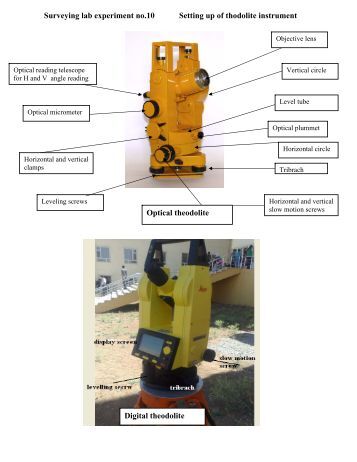
The theodolite is a versatile instrument and is commonly used for the following tasks.
a) Measurement of horizontal angles
b) Measurement of vertical angles
c) Setting out horizontal angles
d) Ranging
e) Levelling
f) Optical distance measurement
g) Controlling verticality
Measurement of horizontal angles
The reiteration method is a common method of observing horizontal angles. The procedure is as follows:
a) Accurately center and level the theodolite over a ground mark
b) Sight the left hand target (face left) with a small reading on the plate using the lower plate clamp and slow motion screw. Do not touch the lower plate again
during this round of angles. If several rounds of angles are to be observed, the initial plate setting is changed by about 90 each time.
c) Sight on to the right hand target(s) using the upper plate clamp and slow motion screw, noting the reading each time.
d) When the last target has been sighted, change face, This is done by rotating the telescope vertically through 180 and the upper plate horizontally though
180 to sight back onto the last target.
e) If face right re-observe all the targets.
f) It is essential that the plate readings are checked for accuracy on completion of each round of angles. Check that there is 180 difference between the
readings. Any variation from the 180 difference is an indication of instrumental error and should be reasonably constant. This will discover gross errors due to
misreading scales, using wrong slow motion screws, sighting wrong targets, etc. The targets can be re-sighted and the readings corrected before changing the
lower plate.
g) Horizontal plate readings and reduced angles can be recorded in a standard field book.
Note the different initial plate settings for each round, the use of the remarks column and the summary of angles.
The operation of one second theodolites is practically the same as that outlined above. The only difference occurs during the initial sighting of the left hand target.
Sight the target first and then set the required plate reading.
Measurement of vertical angles
Vertical angles are useful in applying slope corrections to distance measurement and for determining reduced levels of inaccessible points.
The observing procedure is practically the same for all theodolites.
a) Sight the target with the horizontal cross wire.
b) Level the altitude bubble, unless the instrument has automatic vertical indexing in which case there may be a release button to press
c) After adjusting the micrometer note the plate reading.
d) Change face and repeat
The orientation of the vertical circle varies from one instrument to another and several examples are in Figure 6. Study your theodolite carefully as it is
necessary to reduce vertical angles.
Lesson Note On theodolite - Levelling Methods Part B
Levelling

The theodolite could be used for leveling provided a number of precautions are taken.
a) The altitude bubble should be centred and the telescope locked with a vertical angle of exactly 00-00-00,
b) Read the staff.
a) Change face and repeat the above steps
b) The mean of the two staff readings will give a reasonable result over short distances.
Levelling by theodolite must never be regarded as an acceptable alternative to the surveyor’s level where accuracy is needed.
Optical distance measurement
Horizontal distances can be measured using theodolite and leveling staff. These distances can be accurate to 0.1 m and cannot be used where accuracy is
required.
4 Sight a vertically held leveling staff and read the staff where it is cut by the horizontal crosswire and the two stadia hairs.
5 Check the staff readings. The difference between center and top readings should equal difference between centre and bottom readings. Read the staff again if there is a disagreement.
6 Note the vertical angle after levelling the altitude bubble.
7 Compute the horizontal distance from
100 xsxcos2 vertical angle
where s= difference between top and bottom stadia readings
Subscribe to:
Posts (Atom)