Tuesday 19 December 2017

Describe the different surveys to be carried out for the highway projects.

Describe the different surveys to be carried out for the highway projects.
i) Reconnaissance
ii) Preliminary Survey
iii) Location Survey
i) Reconnaissance:
During the reconnaissance survey the following factors have to be taken into consideration.
Ø Obstructions along the route.
Ø Gradients and length of curves.
Ø Cross drainage works.
Ø Soil type along the route.
Ø Sources of construction materials and
Ø Type of terrain.
ii) Preliminary Survey:
The preliminary survey in a highway project is done with the main objectives
Ø Various alternate arrangements
Ø Estimate the quantity of earth work materials and other construction aspects
Ø Compare different proposals.
The following surveys are constructed
Ø Primary transverse
Ø Topographical surveys
Ø Levelling work
Ø Hydrological data
Ø Soil surveys.
iii) Location Survey:
The final alignment decided after the preliminary survey is to be first located on the field by
establishing the centre line. Next the detailed survey should be carried out.
The detailed survey involves:
Ø Fixing temporary bench marks along the route for every 300 m.
Ø The cross sectional details are taken for 30 m on either side of the central line.
Ø All details of cross drainage works are taken.
Ø Topographical details are taken.

Ø Detailed soil survey is carried out.

Explain the methods of transferring reduced levels from surface to underground in a tunnel setting out work.

Explain the methods of transferring reduced levels from surface to underground in a tunnel setting out work. 

i) Setting out central line of tunnel
ii) Setting out inside tunnels
iii) Transferring of alignment through shafts

i) Setting out central line of tunnel:
The centre-line of tunnels are fixed on the surface along with shaft locations.
Generally the surface control points of the tunnels are not visible from each other. However, by the method of reciprocal ranging points on the summit can be established which can be joined to get the central line. The measurements should be made accurately. Linear measurements are made using invar substance bars with an accuracy of 1 in 10000. Angular measurements are made using 1 second theodolite with an accuracy 0f 15√ N where N is the number of angles. In case of N tunnels in hilly regions it is neither feasible to align the tunnel ends by direct ranging or reciprocal ranging. In such cases precise triangulation has to be used.
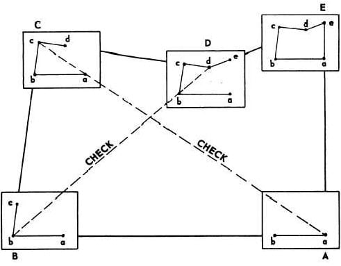
The figure shows a scheme of triangulation network with QR as base line for a tunnel
project. Here all the angles are measured accurately by one second theodolite. Usual corrections for length, temperature, terrain, sag and reduction of levels with respect to sea level are all followed in arriving at the values of the coordinates. The traverse is adjusted for angles and coordinates. The proposed tunnel axis is shown in figure as HR.

ii) Setting out Inside Tunnels:
After the coordinates of portals and shafts are finalized, setting out is started. Centre line of
tunnel is done as shown in figure from various portals and shafts.
Back sighting on the pillar, aligned and constructed as far as practicable on the extended
centre line such as pillar C and then by transiting. Reference points are constructed on the roof of tunnels or slightly below the invert for every 300 m.

iii) Transferring of alignment through shafts:
Transfer of alignment is done through shafts by adopting any one of the following methods:
i) By hanging two or more plumb lines down the shaft.
ii) By lighting directly from edge of shaft where shaft diameter to depth ratio is high.
Co-planning is done by hanging two or more plumb lines down the shaft and determining
the bearing of the plumb planes so formed which are connected to the surface. The plumb lines
should be well apart as for as possible. The plumb lines are of special type. The line shall be of
fine steel wire and carrying a symmetrical weight of 35 kg or more. The wire should be well
stretched to keep it tight. In order to keep the wires vertical, the bob should be contained in a
canister with a hood. This arrangement will shield the bob and will reduce oscillations set up by air currents or by water dropping down the shafts. The canister can be filled with water or oil to reduce the vibrations. The bearing of the plumb plane underground is assumed same as at the surface.
This forms the starting direction for the underground survey work.

The following procedure is adopted for transferring the centerline from top.
Ø A theodolite is set up on top of the hill at a suitable position to maintain the centre line of theshaft.
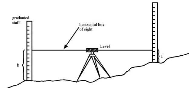
Ø The RLs of both the ends of the shaft are determined by a level. Knowing the bottom RLs ofthe ends the depth of the shaft is found.
Ø Excavation of the shaft is started and verticality is maintained with the help of the plumb-bob which is suspended from wires from top through pulleys.
Ø The excavation is continued until the required bottom level is reached. The depth of the shaft is measured by measuring the length of suspended wire.
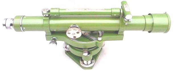
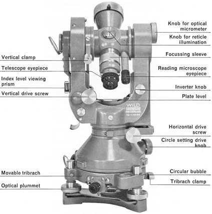
Ø The centre line inside the tunnel is maintained by a precise theodolite. This type of
theodolites are provided with an artificial illumination system to enable work at night and in
the darkness of the tunnel.
Ø It should be properly taken care to see that the centre line is maintained from both ends and one transferred from top coincide.


Thursday 23 November 2017

Types of GIS

Types of GIS 
The following GIS types are not
necessarily mutually exclusive and a GIS application can be always classified under more
than one type.
2.1 Four-dimensional GIS
While spatio-temporal georepresentations can handle two dimensions of
space and one of time, four-dimensional GIS are designed for three dimensions of space and one
of time.
2.2 Multimedia/hypermedia GIS
Multimedia/hypermedia GIS allow the user to access a wide range of georeferenced
multimedia data (e.g., simulations, sounds and videos) by selecting resources from a
georeferenced image map base. A map serving as the primary index to multimedia data in a
multimedia geo-representation is termed a hypermap. Multimedia and virtual georepresentations
can be stored either in extended relational databases, object databases or in
application-specific data stores.
2.3 Web GIS
Widespread access to the Internet, the ubiquity of browsers and the explosion of
commodified geographic information has made it possible to develop new forms of multimedia
geo-representations on the Web.
Many current geomatics solutions are Web-based overtaking the traditional Desktop
environment and most future ones are expected to follow the same direction.
2.4 Virtual Reality GIS
Virtual Reality GIS have been developed to allow the creation, manipulation
and exploration of geo-referenced virtual environments, e.g., using VRML modelling
(Virtual Reality Modelling Language). Virtual Reality GIS can be also Web-based. Applications
include 3D simulation for planning (to experiment with different scenarios).

Monday 30 October 2017

Different Types of Levels Used for Leveling in Surveying

Different Types of Levels Used for Leveling in Surveying


There are various types of levels for leveling in surveying. The process of measuring vertical distances in surveying is called leveling.


To perform leveling, we need some level instruments to focus or to read the object. Nowadays, the technology also introduced in surveying and so many easy measuring instruments are designed. Here we discuss about the different levels used in leveling.

Types of Levels Used in Leveling

Following are the types of different levels used for leveling in surveying:

Dumpy level


Y level


Cushing’s level


Tilting level


Cooke’s reversible level


Automatic level


Dumpy Level

Dumpy level is the most commonly used instrument in leveling. In this level the telescope is restricted against movement in its horizontal plane and telescope is fixed to its support. A bubble tube is provided on the top of the telescope.

But however, the leveling head can be rotated in horizontal plane with the telescope. The telescope is internal focusing telescope is a metal tube contains four main parts as given below.

Objective lens


Negative lens


Diaphragm


Eye-piece


Objective Lens

Objective lens should be made as the combination of crown glass and flint glass. Because of this some defects like spherical aberration and chromatic aberration can be eliminated. A thin layer coating which has smaller refractive index than glass is provided on the objective lens to reduce the loss due to reflection.

Negative Lens

Negative lens located co axial to the objective lens. So, the optical axis for both lenses is same.

Diaphragm

Diaphragm is fitted inside the main tube which contains cross hairs (vertical and horizontal) and these are adjusted by capstan headed screws. The cross hairs are made of dark metal as filament wires which are inserted in diaphragm ring in exact position. For stadia leveling purposes, extra two horizontal cross hairs are provided above and below the horizontal wire.

Eyepiece

Eyepiece lens enable the ability to sight the object together with cross hairs. The image seen through eye piece is magnified and inverted. Some eyepieces erect the image into normal view and those are called as erecting eyepieces.

Y Level

Y level or Wye-level consists y-shaped frames which supports the telescope. Telescope cane be removed from the y-shaped supports by releasing clamp screws provided. These y-shaped frames are arranged to vertical spindle which helps to cause the rotation of telescope.

Compared to dumpy level, adjustments can be rapidly tested in y- level. But, there may be a chance of frictional wear of open parts of level.

Cushing’s Level

In case of Cushing’s level, the telescope is restricted against rotation in its longitudinal axis and it is non-removable. But, the object end and eye piece end can be interchangeable and reversible.

Tilting Level

Tilting level consist a telescope which enabled for the horizontal rotation as well as rotation about 4 degree in its vertical plane. Centering of bubble can be easily done in this type of level. But, for every setup bubble is to be centered with the help of tilting screw.

The main advantage of tilting level is it is useful when the few observations are to be taken with one setup of level.

Cooke’s Reversible Level

Cooke’s reversible level is the combination of dumpy level and y-level. In this instrument, the telescope can be reversed without rotation the instrument. Collimation error can be eliminated in this case because of bubble left and bubble right reading of telescope.

Automatic Level

Automatic level is like the dumpy level. In this case the telescope is fixed to its supports. Circular spirit can be attached to the side of the telescope for approximate leveling. For more accurate leveling, compensator is attached inside the telescope.

Compensator can help the instrument to level automatically. Compensator is also called as stabilizer which consists two fixed prisms and it creates an optical path between eye piece and objective.

Due to the action of gravity, the compensator results the optical system to swing into exact position of line of sight automatically. But before the process of leveling, compensator should be checked.

To check the compensator, just move the foot screws slightly if the leveling staff reading remains constant then compensator is perfect. If it is not constant, then tap the telescope gently to free the compensator. Automatic level is also called as self-adjusting level.

Types of Leveling Methods used in Surveying

Types of Leveling Methods used in Surveying


There are various types of leveling used in surveying for measurement of level difference of different points with respect to a fixed point. This is useful in various civil engineering construction works where levels of different structures need to be maintained as per drawing.


What Is Leveling?

Leveling is a branch of surveying in civil engineering to measure levels of different points with respect to a fixed point such as elevation of a building, height of one point from ground etc.

Types of Leveling in Surveying

Direct leveling


Trigonometric leveling


Barometric leveling


Stadia leveling


Direct Leveling

It is the most commonly used method of leveling. In this method, measurements are observed directly from leveling instrument.

Based on the observation points and instrument positions direct leveling is divided into different types as follows:

Simple leveling


Differential leveling


Fly leveling


Profile leveling


Precise leveling


Reciprocal leveling


Simple Leveling

It is a simple and basic form of leveling in which the leveling instrument is placed between the points which elevation is to be find. Leveling rods are placed at that points and sighted them through leveling instrument. It is performed only when the points are nearer to each other without any obstacles.

Differential Leveling

Differential leveling is performed when the distance between two points is more. In this process, number of inter stations are located and instrument is shifted to each station and observed the elevation of inter station points. Finally difference between original two points is determined.

Fly Leveling

Fly leveling is conducted when the benchmark is very far from the work station. In such case, a temporary bench mark is located at the work station which is located based on the original benchmark. Even it is not highly precise it is used for determining approximate level.

Profile Leveling

Profile leveling is generally adopted to find elevation of points along a line such as for road, rails or rivers etc. In this case, readings of intermediate stations are taken and reduced level of each station is found. From this cross section of the alignment is drawn.

Precise Leveling

Precise leveling is similar to differential leveling but in this case higher precise is wanted. To achieve high precise, serious observation procedure is performed. The accuracy of 1 mm per 1 km is achieved.

Reciprocal Leveling

When it is not possible to locate the leveling instrument in between the inter visible points, reciprocal leveling is performed. This case appears in case of ponds or rivers etc. in case of reciprocal leveling, instrument is set nearer to 1st station and sighted towards 2nd station.

Trigonometric Leveling

The process of leveling in which the elevation of point or the difference between points is measured from the observed horizontal distances and vertical angles in the field is called trigonometric leveling.

In this method, trigonometric relations are used to find the elevation of a point from angle and horizontal distance so, it is called as trigonometric leveling. It is also called as indirect leveling.

Barometric Leveling

Barometer is an instrument used to measure atmosphere at any altitude. So, in this method of leveling, atmospheric pressure at two different points is observed, based on which the vertical difference between two points is determined. It is a rough estimation and used rarely.

Stadia Leveling

It is a modified form of trigonometric leveling in which Tacheometer principle is used to determine the elevation of point. In this case the line of sight is inclined from the horizontal. It is more accurate and suitable for surveying in hilly terrains.

TOTAL STATION –OPERATION, USES & ADVANTAGES


TOTAL STATION –OPERATION, USES & ADVANTAGES


What is a Total Station?


Total station is a surveying equipment combination of Electromagnetic Distance Measuring Instrument and electronic theodolite. It is also integrated with microprocessor, electronic data collector and storage system. The instrument can be used to measure horizontal and vertical angles as well as sloping distance of object to the instrument.


Capability of a Total Station:


Microprocessor unit in total station processes the data collected to compute:


Average of multiple angles measured.


Average of multiple distance measured.


Horizontal distance.


Distance between any two points.


Elevation of objects and


All the three coordinates of the observed points.


Data collected and processed in a Total Station can be downloaded to computers for further processing.


Total station is a compact instrument and weighs 50 to 55 N. A person can easily carry it to the field. Total stations with different accuracy, in angle measurement and different range of measurements are available in the market. Figure below shows one such instrument manufactured by SOKKIA Co. Ltd. Tokyo, Japan.


Fig: Parts of total station


Brief Description of Important Operations of Total Station:


Distance Measurement:


Electronic distance measuring (EDM) instrument is a major part of total station. Its range varies from 2.8 km to 4.2 km. The accuracy of measurement varies from 5 mm to 10 mm per km measurement. They are used with automatic target recognizer. The distance measured is always sloping distance from instrument to the object. Angle Measurements: The electronic theodolite part of total station is used for measuring vertical and horizontal angle. For measurement of horizontal angles any convenient direction may be taken as reference direction. For vertical angle measurement vertical upward (zenith) direction is taken as reference direction. The accuracy of angle measurement varies from 2 to 6 seconds.


Data Processing :


This instrument is provided with an inbuilt microprocessor. The microprocessor averages multiple observations. With the help of slope distance and vertical and horizontal angles measured, when height of axis of instrument and targets are supplied, the microprocessor computes the horizontal distance and X, Y, Z coordinates. The processor is capable of applying temperature and pressure corrections to the measurements, if atmospheric temperature and pressures are supplied.


Display:


Electronic display unit is capable of displaying various values when respective keys are pressed. The system is capable of displaying horizontal distance, vertical distance, horizontal and vertical angles, difference in elevations of two observed points and all the three coordinates of the observed points.


Electronic Book:


Each point data can be stored in an electronic note book (like compact disc). The capacity of electronic note book varies from 2000 points to 4000 points data. Surveyor can unload the data stored in note book to computer and reuse the note book.


Use of Total Station


The total station instrument is mounted on a tripod and is levelled by operating levelling screws. Within a small range instrument is capable of adjusting itself to the level position. Then vertical and horizontal reference directions are indexed using onboard keys. It is possible to set required units for distance, temperature and pressure (FPS or SI). Surveyor can select measurement mode like fine, coarse, single or repeated.


When target is sighted, horizontal and vertical angles as well as sloping distances are measured and by pressing appropriate keys they are recorded along with point number. Heights of instrument and targets can be keyed in after measuring them with tapes. Then processor computes various information about the point and displays on screen.


This information is also stored in the electronic notebook. At the end of the day or whenever electronic note book is full, the information stored is downloaded to computers.


The point data downloaded to the computer can be used for further processing. There are software like auto civil and auto plotter clubbed with AutoCad which can be used for plotting contours at any specified interval and for plotting cross-section along any specified line.


Advantages of Using Total Stations


The following are some of the major advantages of using total station over the conventional surveying instruments:


Field work is carried out very fast.


Accuracy of measurement is high.


Manual errors involved in reading and recording are eliminated.


Calculation of coordinates is very fast and accurate. Even corrections for temperature and pressure are automatically made.


Computers can be employed for map making and plotting contour and cross-sections. Contour intervals and scales can be changed in no time.


However, surveyor  should check the working condition of the instruments before using. For this standard points may be located near survey office and before taking out instrument for field work, its working is checked by observing those standard points from the specified instrument station.


Surveying Principles and Methods in Civil Engineering

Surveying Principles and Methods in Civil Engineering


Surveying is the process of determining relative positions of different objects on the surface of the earth by measuring horizontal distances between them and preparing a map to any suitable scale.


Measurements are taken in horizontal plane only. Surveying is the art of determining the relative positions of points on, above or beneath the surface of the earth by means of direct or indirect measurements of distance, direction and elevation.

Leveling is a branch of surveying the object of which is to find the elevations of points with respect to a given or assumed datum and to establish points at a given elevation or at different elevations with respect to a given or assumed datum.

Survey is performed to prepare a map of relative positions on surface of the earth. It shows the natural feature of a country such as towns, villages, roads, railways, etc. They may also include details of different engineering works such as bridge, canal, dam etc.

Before commencement of any major engineering project, survey is carried out to determine the location of site and its surrounding. To understand the topography of the site and natural resource availability. Survey is carried out to prepare the cadastral map showing property boundaries.

Principles of Surveying

The fundamental principle upon which the various methods of plane surveying are based can be stated under the following two aspects.

Location of a point by measurement from two points of reference

According to this principle, the relative position of a point to be surveyed should be located by measurement from at least two points of reference, the positions of which have already been fixed.

If P and Q are the two reference points on the ground, any other point, such as R, can be located by any of the direct methods shown in the above figures. But, although a single method is sufficient to locate the relative position of ‘R’ with respect to reference points P and Q, it is necessary to adopt at least any two methods to fix the position of point ‘R’.

While the measurements made in the either of the first method or second method will be helpful in locating the point ‘R’, the measurements made in the other method will act as a check.

Working from whole to part

According to this principle, it is always desirable to carryout survey work from whole to part. This means, when an area is to be surveyed, first a system of control points is to be established covering the whole area with very high precision. Then minor details are located by less precise methods.

The idea of working this way is to prevent the accumulation of errors and to control and localize minor errors which, otherwise, would expand to greater magnitudes if the reverse process is followed, thus making the work uncontrolled at the end.

Method of Surveying in Civil Engineering

Method of Surveying in Civil Engineering


Primary types of Surveying are:


Plane surveying


Geodetic surveying


1. Plane surveying


Plane surveying is conducted by state agencies as well as private agencies. As we know earth is spherical in shape but its diameter is big enough to consider plane in small dimensions. It is that type of surveying in which the mean surface of the earth is considered as a plane and the spheroidal shape is neglected. All triangles formed by survey lines are considered as plane triangles. The level line is considered as straight and plumb lines are considered parallel. Plane surveying is done of the area of survey is less than 250 km2.


2. Geodetic surveying


Geodetic survey is conducted by survey department of the country. It is that type of surveying in which the curved shape of the earth is taken in to account. The object of geodetic survey is to determine the precise position on the surface of the earth, of a system of widely distant points which form control stations in which surveys of less precision may be referred. . Line joining two points is considered as curved line and angles are assumed as spherical angles. It is carried out if the area exceeds over 250 km2.


Secondary classification of Surveying


Surveys may be classified based on the nature of the field of survey, object of survey and instruments used.


1) Surveying based on Nature of Survey


a) Topographical Surveys


They are carried out determine the position of natural features of a region such as rivers, streams, hills etc. and artificial features such as roads and canals. The purpose of such surveys is to prepare maps and such maps of are called topo-sheets.


b) Hydrographic Survey


Hydro-graphic survey is carried out to determine M.S.L. (Mean Sea Level), water spread area, depth of water bodies, velocity of flow in streams, cross-section area of flow etc.


c) Astronomical Survey


The Astronomical Survey is carried out to determine the absolute location of any point on the surface of earth. The survey consists of making observations to heavenly bodies such as stars.


d) Engineering Survey


This type of survey is undertaken whenever sufficient data is to be collected for the purpose of planning and designing engineering works such as roads, bridges and reservoirs.


e) Archeological Survey


This type of survey is carried out to gather information about sites that are important from archeological considerations and for unearthing relics of antiquity.


f) Photographic Survey


In this type of survey, information is collected by taking photographs from selected points using a camera.


g) Aerial Survey


In this type of survey data about large tracks of land is collected by taking photographs from an aero-plane.


h) Reconnaissance Survey


In this type of survey, data is collected by marking physical observation and some measurements using simple survey instruments.


2) Surveying based on Type of Instruments


a) Chain Surveying


Chain surveying is the basic and oldest type of surveying. The principle involved in chain survey is of triangulation. The area to be surveyed is divided into a number of small triangles. Angles of triangles must not be less than 30 degree and greater than 120 degree. Equilateral triangles are considered to be ideal triangles. No angular measurements are taken, tie line and check lines control accuracy of the work.


This method is suitable on level ground with little undulations and area to be survey is small.


b) Compass Surveying


Compass survey uses the principle of traversing. This method does not requires the need to create triangles. It uses a prismatic compass for measuring magnetic bearing of line and the distance is measured by chain. A series of connecting lines is prepared using compass and measuring distances using chain. Interior details are located using offset from main survey lines.


They suitable for large area surveying crowded with many details. It can be used to survey a river course.


The principle of plane table survey is parallelism. They are plotted directly on paper with their relative position. The rays are drawn from station to object on ground. The table is placed at each of the successive station parallel to the position of the last station.


They are basically suitable for filling interior detailing and is recommended when great accuracy is not required.


d) Theodolite Surveying


The theodolite is an instrument used mainly for accurate measurement of the horizontal and vertical angles. They are accurate to measure up to 10″ or 20″ angles.


Theodolite can be used to measure:


Horizontal angles


Vertical angles


Deflection angle


Magnetic bearing


Horizontal distance between two points


Vertical height between two points


Difference in elevation


Nowadays theodolite is shadowed and replaced by the use of Total Station which can perform the same task with greater ease and accurate results


e) Tacheometric Surveying


Tacheometry is a branch of surveying in which horizontal and vertical distances are determined by taking angular observations with an instrument known as a tacheometer. Tacheometer is nothing but a transit theodolite fitted with a stadia diaphragm and an anallatic lens. There is no need for chaining in such survey. The principle of Tacheometer is based on property of isosceles triangle, where ratio of the distance of the base from the apex and the length of the base is always constant.


Different form of stadia diaphragm commonly used:


f) Photographic Surveying


Photographic survey is based on technique of taking photographs from different angle to prepare topographic details with relative high speed.


Saturday 9 September 2017

Basic Digitization in ArcGIS

Make 3D with ArcGis 10.2

ArcGis 3d analyst Draping an image over a terrain surface

ArcGIS10 Basics 4b of 4

ArcGIS10 Basics 4b of 4

ArcGIS10 Basics 4a of 4

ArcGIS10 Basics 4a of 4

ArcGIS10 Basics 3b of 4

ArcGIS10 Basics 3a of 4

ArcGIS10 Basics 2 of 4

ArcGIS10 Basics 1 of 4

A Basic Introduction to ArcMap 10

Adding XY Data

Importing data from excel to ArcGIS

How georeferencing a scanned map in ArcGIS 9.3

Introdution to Arcgis 9.3.mp4

ArcGIS 9.3 Tutorial

How to make 3D model using Arcgis, GIS in 3D

arcgis 9 3 lessen 5

arcgis 9 3 lessen 4

arcgis 9 3 lesson 3

ArcGIS 9.3 lesson 2

arcgis 9.3 lesson 1

AutoCAD Civil 3D 2011 - Corridor Editing

Civil 3D Intersection Design Tools

Five Minute Road Design using RoadEng

Advanced Road Design - Drainage and Sewer Design Overview

Sunday 11 June 2017

Traverse Correction - Bowditch Method

Traverse Correction - Bowditch Method


In Traversing the lengths of the line are measured by chain or a tape and the directions are fixed by the compass or theodolite or by forming angles with chain and a tape. The latest instruments like total station captures the co-ordinates of the points along with elevations. These instruments are also capable of recording and string the distances and angles replacing the conventional methods.
There are two types of traverse surveying i.e. Closed Traverse and Open Traverse.
  1. Closed Traverse
    When a series of connected lines form a closed circuit, ie. When the finishing point coincides with the starting point, then it is called as a closed traverse. These closed traverse surveys has many applications like fixing the boundaries of ponds, forests etc..

  1. Open traverse :
    When a sequence of connected lines extends along a general direction and does not return to the starting point, it is known as ‘open traverse’ or ‘unclosed traverse’.

Traverse Correction Procedure
Present techniques used in traversing using total station as a open traverse. The steps are as described below…
  1. GPS pair points are fixed at a convenient distance, approximately about 3 to 5km. Care has to be taken that the pair of GPS points is fixed at a reliable distance (at least 60m is advised for better results) and on good monuments. These points are fixed in such a way that they are clearly inter visible and should cater for placing the total station firmly on the GPS stations,
  2. Total station is to be checked for its calibration, prism constants for the prisms to be set in the instrument to avoid errors.
  3. Total station is then used to conduct the traverse between the GPS points. This type of traverse ensures that the survey is started from a known pair of points and is closed on known pair of points. Care has to be taken that the last bearing is also taken for correcting the misclosures.
  4. There are several methods to correct the traverse misclosures. However, in most of the cases Bowditch rule is considered to be most reliable. The other methods like transit method, Crandall method, Least Square Methods are used very rarely. The most accurate method which is known as a misclosures correction by the least square method is used when the accuracy required is very high. This method finds itself applicable in the projects like tunnel works.
  1. Bowditch Rule
  2. Whole Circle Bearing
  3. Quandrantal Bearing

TOTAL STATION TRAVERSING ADJUSTMENT BY BOWDITCH METHOD

TOTAL STATION TRAVERSING ADJUSTMENT BY BOWDITCH METHOD


PROCEDURE FOR TRAVERSE CALCULATIONS

  • Adjust angles or directions
  • Determine bearings or azimuths
  • Calculate and adjust latitudes and departures
  • Calculate rectangular coordinates

DETERMINING BEARINGS OR AZIMUTHS

  • Requires the direction of at least one line within the traverse to be known or assumed
  • For many purposes, an assumed direction is sufficient
  • A magnetic bearing of one of the lines may be measured and used as the reference for determining the other directions
  • For boundary surveys, true directions are needed

LATITUDES AND DEPARTURES

Traverse Correction - Bowditch Method

Line
Dir
Deg
Min
Sec
Dir
Degrees
Length
Cumulative
Length
Azimuthal
Angles
Departure
Latitude
AB
N
26
10
0
E
N26.167E
285.1
285.1
26.167
+125.726
+255.881
BC
S
75
25
0
E
S75.417E
610.45
895.55
+104.583
+590.784
-153.700
CD
S
15
30
0
W
S15.5W
720.48
1616.03
+195.500
-192.540
-694.276
DE
N
1
42
0
W
N1.7W
203
1819.03
+358.300
-6.022
+202.911
EA
N
53
0
0
W
N53W
647.02
2466.05
+307.000
-516.733
+389.386

CLOSURE OF LATITUDES AND DEPARTURES

  • The algebraic sum of all latitudes must equal zero or the difference in latitude between the initial and final control points
  • The algebraic sum of all departures must equal zero or the difference in departure between the initial and final control points

ADJUSTMENT OF LATITUDES AND DEPARTURES


Line
Dir
Deg
Min
Sec
Dir
Length
Cumulative
Length
Azimuthal
Angles
Departure
Latitude
AB
N
26
10
0
E
285.1
285.1
26.167
+125.726
+255.881
BC
S
75
25
0
E
610.45
895.55
+104.583
+590.784
-153.700
CD
S
15
30
0
W
720.48
1616.03
+195.500
-192.540
-694.276
DE
N
1
42
0
W
203
1819.03
+358.300
-6.022
+202.911
EA
N
53
0
0
W
647.02
2466.05
+307.000
-516.733
+389.386
Correctioning Latitude 

ADJUSTED LATITUDES AND DEPARTURES


Line
Dir
Deg
Min
Sec
Dir
Length
Cumulative
Length
Azimuthal
Angles
Departure
Misclosure
Latitude
Misclosue
Corrected
Departure
Corrected
Latitude
AB
N
26
10
0
E
285.1
285.1
26.167
+0.140
+0.023
+125.586
+255.858
BC
S
75
25
0
E
610.45
895.55
+104.583
+0.301
+0.050
+590.483
-153.750
CD
S
15
30
0
W
720.48
1616.03
+195.500
+0.355
+0.059
-192.895
-694.335
DE
N
1
42
0
W
203
1819.03
+358.300
+0.100
+0.017
-6.122
+202.894
EA
N
53
0
0
W
647.02
2466.05
+307.000
+0.319
+0.053
-517.052
+389.334
                                                                                                                                                αCorr.Dep=0      αCorr.Lat=0
The Sum of total Corrected Departure and Sum of total Corrected latitude is 0.00, proves that the traverse is balanced

RECTANGULAR COORDINATES

  • Rectangular X and Y coordinates of any point give its position with respect to a reference coordinate system
  • Useful for determining length and direction of lines, calculating areas, and locating points
  • You need one starting point on a traverse (which may be arbitrarily defined) to calculate the coordinates of all other points
  • A large initial coordinate is often chosen to avoid negative values, making calculations easier.

CALCULATING X AND Y COORDINATES

Given the X and Y coordinates of any starting point A, the X and Y coordinates of the next point B are determined by:
Calculate XY

Line
Dir
Deg
Min
Sec
Dir
Length
Azimuthal
Angles
Calculated
Easting
Calculated
Northing
Adjusted
Easting
Corrected
Northing
AB
N
26
10
0
E
285.1
26.167
+5125.726
+10255.881
+5125.586
+10255.858
BC
S
75
25
0
E
610.45
+104.583
+5716.510
+10102.180
+5716.069
+10102.107
CD
S
15
30
0
W
720.48
+195.500
+5523.970
+9407.904
+5523.174
+9407.772
DE
N
1
42
0
W
203
+358.300
+5517.948
+9610.815
+5517.052
+9610.666
EA
N
53
0
0
W
647.02
+307.000
+5001.214
+10000.201
+5000.000
+10000.000

LINEAR MISCLOSURE

The hypotenuse of a right triangle whose sides are the misclosure in latitude and the misclosure in departure.
Linear_Misclosure

TRAVERSE PRECISION

  • The precision of a traverse is expressed as the ratio of linear misclosure divided by the traverse perimeter length.
  • expressed in reciprocal form
  • Example
0.89 / 2466.05 = 0.00036090
1 / 0.00036090 = 2770.8

Precision = 1/2771