
Land Survey, Setting-Out Engineering, GIS Processing, Structural/Civil Works and General Contracts Call +2347064649087 www.heroizutechng.blogspot.com.ng
Showing posts with label Civil Engineering. Show all posts
Showing posts with label Civil Engineering. Show all posts
Friday, 9 August 2019
Sunday, 28 October 2018
Ground Control - aerial photograph Ground Control
Ground Control - aerial photograph
Ground Control
In order to produce an accurate map from aerial photograph it is absolutely necessary to established ground control. It consists in locating the positions of a no of pts. All over the area to be surveyed det their levels. These control pts short be such that can be easily identified on the photographs. Horizontal control is established by tiring or traversing. Vertical control is established through the use of ‘aneroid barometers’ or ‘Altimeters’
Applications of Air Photograph:
The practical uses of air photography are unlimited. Some of the application are listed below:
- Town and country planning and developed estate man agent and economic planning are used both maps based on air survey and individual photography’s.
- suitability of roads and rail alignments can be studied both for traffic flow an economy of construction.
- Forestry and geology both use air maps and photography for the study of nature of areas and changes that take place.
- Flood control planning can be based on air survey made at suitable intervals of time
- Air survey provides means of mapping large undeveloped areas of the world.
- For large scale engineering and redevelopment projects, reconnaissance can be undertake in to a large extend form air photograph.
- Survey for accessing damage due to earth quake, crop dieses can be quickly estimated from air photograph.
- Pollution effects form industrial wastes on land and water can be studied.
Tunnels:
Tunnels are constructed in order
- To meet the req of rapid transportation in big cities.
- To connect by shortest route, two termination separated by mountain.
- To reduce very steep grades.
- To avoid the excessive cost of mantaineice of an open cut subjected to land slides or snow drifts.
- To avoid the expensive acquisition of valuable built up land, tearing up pavements and holding up traffic for long periods in large cities
- When the depth of ordinary cutting exceeds 20m and the ground rises rapidly for a considerable distance after wards.
Chief considerations in location of a tunnel are
- If should follow the best line adopted to the proposed traffic.
- If should be most economical in construction an operation.
- Convenience Ingress (enter) and Egress (leave)
Tunneling involves the following operatios:
- Surface Survey
- Transferring the alignment under ground
- Transferring levels under ground
SURFACE SURVERY:
This includes
- A preliminary survey by transit and staid for 2-3miles (3-4km) on either side of the proposed alignment.
- A plan (map) with a scale of say 1 in with contours drawn at 5m (20) intervals.
- Final alignment is selected form this plan.
- A detail survey of the geological information of strata as the cost of tunneling depends upon the nature of materials to be encountered.
The proposed route having been decided upon, the following pts require consideration.
- Alignment of the centre line of the tunnel.
- Gradient to be adopted.
- Determination of the exact length of tunnel.
- Establishment of permanent stations marking the line.
Control surveys for tunnel layouts are performed on ht surface joining the terminal pts of the tunnel is shown in figure (1).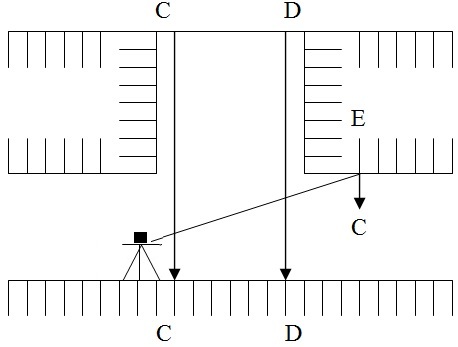
Transferring the alignment under ground:
This is the most difficult and important operation in setting out a tunnel.
- Fix two timber beams C and D as shown in figure two across the top of the shaft near its edges perpendicular to the direction of tunnel and as far apart as possible.
- A threadlike is set up at a ground at a pre-determined station on a centre. Line mark one ground surface and another stations is again on the centre line itself.
- The centre line is very carefully set up on the beams preferably on the plates fixed on a beam and drilled with hole for suspending wires by repetition observing and averaging the result.
- From these pts two long penal wire with heavy plumb hobs 10 to 15 kg attacked to their lower edges or suspended down the shaft.
- At the bottom these plumb bobs are immured in bucket of water, oil etc to eliminate oscillation.
- Great care must be taken that wires and plumb bobs are hanging free. As a check the dist b/w the wires at the top and at the bottom of the shaft is to be measured and this should be the same.
- The line joining the two wires gives the dir of alignment under ground.
- The theodolite is transfer to the bottom of shaft and through the no of trails suspended wires.
- Now the alignment is marked on marks driven into the whole i.e, E drilled on the roof.
Transferring levels under ground:
Leveling on the surface is done in the usual way and the levels are transfer underground at the ends of the tunnel from the nearest bench mark.
In case of transfer of levels underground at the shaft. The steps involve are
- A fine steel wire loaded with weight of 5 to 15 kg is passed over a pulley (w) at the top of the shaft and is lowered into the shaft as shown in fig.3
- Tow fine wire AA and BB horizontally stretched at the top and bottom of the shaft rasp.
- The steel wired lowered into the shaft is so adjusted that it is in contact with both the wires AA and BB.
- The pts of contact are marked on a still wire by a piece of chalk or by some other marker.
- The wire is withdrawn form the shaft and is stretched on the ground.
- The dist b/t the two marks on he wire is measured using the measuring tape and this gives the level of the bottom of the shaft.
LATTIUDE AND LONGITUDE:
O = Centre of earth
N = North Pole
S = South Pole
Nos = Polar axis or polar diameter about which earth rotates.
A = Any point on surface of earth
The position of a place on the earth surface is specified by latitude and longitude. The semi circle ‘NAS’ passing through A and terminates by the Poles N and S is called Meridian of the place.
LATITUDE:
Latitude of a place is the angular distance measured from the equator towards the nearer Pole along the meridian of the place or latitude of any pt ‘A’ is angle or arc AA’’. Latitude can also be defined as the angular distance that the place is north or south of equator.
The earth sphere being divided into two hemispheres by the equator, the upper one containing the North Pole is called the northern hemisphere. While the lower one having the South Pole is called southern hemisphere. The place is said to have a north latitude if it is in the northern hemisphere and south latitude if it is in the southern hemisphere.
The latitude angle is meared (90) at the earth center. North or south from the equatorial plane. Latitude north of equator is considered positive and that south of equator negative.
LONGITUDE:
Longitude of a place is the angular distance b/t the meridian of a place and the standard prime meridian
Or
Longitude of any place ‘A’ is angle ‘LA’ measured in the equatorial plane b/t the standard meridian and the meridian through A.
Or
The meridian NGS passing through Greenwich England has been adopted internationally as the standard meridian. This meridian divides the sphere into two hemispheres. The longitude is measured from “O” to 180 either towards east or west. The west longitude is considered as positive and the east as negative. Longitude angles are measured at the earth centre east or west from the plane of ‘O’ longitude which has been arbitrary placed through green witch England.
Hence the position of place ‘A’ is completely specified by the latitude and longitude. These two terms give unique location of any pt on the earth. This system of geographic co-ordinates is used in navigation and Geodesy.
Thursday, 29 March 2018
How do I georeference an image in ArcGIS?
Q: How do I georeference an image in ArcGIS?
Answer
Georeferencing is a process by which a
raster dataset (image) without spatial reference can be matched with a
layer that does have spatial reference. For example, this process would
be helpful in the case of a user finding an aerial photograph in their
map.
In ArcMap, add a reference layer to your map that would be
helpful in matching points from the image (e.g. streets if you have an
aerial photograph of a city) or a basemap (click the dropdown arrow next
to the Add Data button)
Add the image you want to georeference.
Open the Georeferencing toolbar (Customize > Toolbars).
Zoom to the area you will use for georeferencing your
image. Select Fit to Display from the Georeferencing toolbar dropdown
menu to move the image closer to where it should be located.
Add control points using the button with two crosses connected by a line: 
Zoom to your image (right click on the layer > Zoom to
Layer). Add a control point to a place that will be easy to find in the
reference layer, such as a road intersection, bend in a river,
administrative boundary, etc. Zoom in close on the control point site to
maximize your precision.
Zoom to the reference layer, and add the second control
point in the same geographical location. Zoom in close on the control
point site to maximize your precision.
Repeat these steps using points from around your map. Very quickly your image will fit in the map.
When you are finished go to Georeferencing > Rectify to save a new raster dataset that retains the spatial reference.
Helpful hints:
In the Georeferencing dropdown menu, the Transformation options are helpful if your image necessitates more warping.
The blue lines between control points represent the
residual (or, error). The View Link Table button in the toolbar allows
you to look at all of the links you have made, see their respective
residuals, and delete ones you think may be inaccurate.
Saturday, 9 September 2017
Monday, 5 December 2016
History of Civil Engineering
History of Civil Engineering:
 Civil
Engineering has been an aspect of life since the beginnings of human
existence. The earliest practices of Civil engg may have commenced
between 4000 and 2000 BC in Ancient Egypt and Mesopotamia (Ancient Iraq)
when humans started to abandon a nomadic existence, thus causing a need
for the construction of shelter. During this time, transportation
became increasingly important leading to the development of the wheel
and sailing.
Civil
Engineering has been an aspect of life since the beginnings of human
existence. The earliest practices of Civil engg may have commenced
between 4000 and 2000 BC in Ancient Egypt and Mesopotamia (Ancient Iraq)
when humans started to abandon a nomadic existence, thus causing a need
for the construction of shelter. During this time, transportation
became increasingly important leading to the development of the wheel
and sailing.Until modern times there was no clear distinction between civil engg and architecture, and the term engineer and architect were mainly geographical variations referring to the same person, often used interchangeably. The construction of Pyramids in Egypt (circa 2700-2500 BC) might be considered the first instances of large structure constructions.
 Around
2550 BC, Imhotep, the first documented engineer, built a famous stepped
pyramid for King Djoser located at Saqqara Necropolis. With simple
tools and mathematics he created a monument that stands to this day. His
greatest contribution to engineering was his discovery of the art of
building with shaped stones. Those who followed him carried engineering
to remarkable heights using skill and imagination.
Around
2550 BC, Imhotep, the first documented engineer, built a famous stepped
pyramid for King Djoser located at Saqqara Necropolis. With simple
tools and mathematics he created a monument that stands to this day. His
greatest contribution to engineering was his discovery of the art of
building with shaped stones. Those who followed him carried engineering
to remarkable heights using skill and imagination. Ancient historic civil engineering constructions include the Qanat water management system (the oldest older than 3000 years and longer than 71 km,) the Parthenon by Iktinos in Ancient Greece (447-438 BC), the Appian Way by Roman engineers (c. 312 BC), the Great Wall of China by General Meng T’ien under orders from Ch’in Emperor Shih Huang Ti (c. 220 BC) and the stupas constructed in ancient Sri Lanka like the Jetavanaramaya and the extensive irrigation works in Anuradhapura. The Romans developed civil structures throughout their empire, including especially aqueducts, insulae, harbours, bridges, dams and roads.
Other remarkable historical structures are Sennacherib's Aqueduct at Jerwan built in 691 BC; Li Ping's irrigation projects in China (around 220 BC); Julius Caesar's Bridge over the Rhine River built in 55 BC, numerous bridges built by other Romans in and around Rome(e.g. the pons Fabricius); Pont du Gard (Roman Aqueduct, Nimes, France) built in 19 BC; the extensive system of highways the Romans built to facilitate trading and (more importantly) fast manoeuvring of legions; extensive irrigation system constructed by the Hohokam Indians, Salt River, AZ around 600 AD; first dykes defending against high water in Friesland, The Netherlands around 1000 AD; El Camino Real - The Royal Road, Eastern Branch, TX and Western Branch, NM (1500s AD).
 Machu
Picchu, Peru, built at around 1450, at the height of the Inca Empire is
considered an engineering marvel. It was built in the Andes Mountains
assisted by some of history’s most ingenious water resource engineers.
The people of Machu Picchu built a mountain top city with running water,
drainage systems, food production and stone structures so advanced that
they endured for over 500years.
Machu
Picchu, Peru, built at around 1450, at the height of the Inca Empire is
considered an engineering marvel. It was built in the Andes Mountains
assisted by some of history’s most ingenious water resource engineers.
The people of Machu Picchu built a mountain top city with running water,
drainage systems, food production and stone structures so advanced that
they endured for over 500years. A
treatise on Architecture, Book called Vitruvius' De Archiectura, was
published at 1AD in Rome and survived to give us a look at engineering
education in ancient times. It was probably written around 15 BC by the
Roman architect Vitruvius and dedicated to his patron, the emperor
Caesar Augustus, as a guide for building projects.
A
treatise on Architecture, Book called Vitruvius' De Archiectura, was
published at 1AD in Rome and survived to give us a look at engineering
education in ancient times. It was probably written around 15 BC by the
Roman architect Vitruvius and dedicated to his patron, the emperor
Caesar Augustus, as a guide for building projects.Throughout ancient and medieval history most architectural design and construction was carried out by artisans, such as stonemasons and carpenters, rising to the role of master builder. Knowledge was retained in guilds and seldom supplanted by advances. Structures, roads and infrastructure that existed were repetitive, and increases in scale were incremental.
One of the earliest examples of a scientific approach to physical and mathematical problems applicable to civil engineering is the work of Archimedes in the 3rd century BC, including Archimedes Principle, which underpins our understanding of buoyancy, and practical solutions such as Archimedes’ screw. Brahmagupta, an Indian mathematician, used arithmetic in the 7th century AD, based on Hindu-Arabic numerals, for excavation (volume) computations.
Educational & Institutional history of civil engineering
In the 18th century, the term civil engineering was coined to incorporate all things civilian as opposed to military engineering. The first engineering school, The National School of Bridges and Highways, France, was opened in 1747. The first self-proclaimed civil engineer was John Smeaton who constructed the Eddystone Lighthouse. In 1771, Smeaton and some of his colleagues formed the Smeatonian Society of Civil Engineers, a group of leaders of the profession who met informally over dinner. Though there was evidence of some technical meetings, it was little more than a social society.") In
1818, world’s first engineering society, the Institution of Civil
Engineers was founded in London, and in 1820 the eminent engineer Thomas
Telford became its first president. The institution received a Royal
Charter in 1828, formally recognizing civil engineering as a profession.
Its charter defined civil engineering as: “Civil engineering is the
application of physical and scientific principles, and its history is
intricately linked to advances in understanding of physics and
mathematics throughout history. Because civil engineering is a wide
ranging profession, including several separate specialized
sub-disciplines, its history is linked to knowledge of structures,
material science, geography, geology, soil, hydrology, environment,
mechanics and other fields.”
In
1818, world’s first engineering society, the Institution of Civil
Engineers was founded in London, and in 1820 the eminent engineer Thomas
Telford became its first president. The institution received a Royal
Charter in 1828, formally recognizing civil engineering as a profession.
Its charter defined civil engineering as: “Civil engineering is the
application of physical and scientific principles, and its history is
intricately linked to advances in understanding of physics and
mathematics throughout history. Because civil engineering is a wide
ranging profession, including several separate specialized
sub-disciplines, its history is linked to knowledge of structures,
material science, geography, geology, soil, hydrology, environment,
mechanics and other fields.”The first private college to teach Civil Engineering in the United States was Norwich University founded in 1819 by Captain Alden Partridge. The first degree in Civil Engineering in the United States was awarded by Rensselaer Polytechnic Institute in 1835. The first such degree to be awarded to a woman was granted by Cornell University to Nora Stanton Blatch in 1905.
Subscribe to:
Posts (Atom)