Design engineers require specialized software, tools, and apps
to research and develop ideas for new products and their associated
systems. You need to be able to create blueprints and schematics for
structures, systems, machines, and equipment and work collaboratively
with other engineers, drafters, and team members, and you need to be
able to work productively and efficiently. That’s why design engineers’
software, tools, and apps need to streamline your design and development
processes rather than hinder them.
We at Pannam recognize all of the challenges and demands design engineers face, so we have compiled a list of the top engineering design tools, software, and apps in the hopes of making your job a little easier. Our top engineering design picks cover mechanical, electrical, and structural engineering design needs and include CAD programs, simulation tools, modeling tools, digital prototyping software, engineering calculation and conversion tools, pocket reference, and other solutions specifically for design engineering.

Please note, we have listed our top engineering design software, tools, and apps here, in no particular order.
1. Autodesk Product Design Suite
@autodesk

Autodesk is best known for its 3D design and engineering software and services. We like Autodesk Product Design Suite because it is a comprehensive 3D product design solution that offers everything design engineers need, from simulation, to collaboration, to visualization, to digital prototyping tools. Complete your entire engineering process with Autodesk Product Design Suite.
Key Features:
@MATLAB
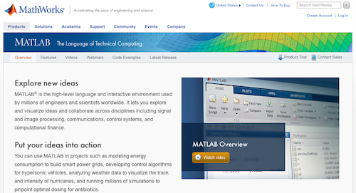
A high-level language and interactive environment for numerical computation, visualization, and programming, MATLAB is an engineering design tool preferred by millions of engineers and scientists worldwide. With MATLAB, you can explore and visualize ideas and collaborate across disciplines to put your ideas into action.
Key Features:
@3DSATIA

A Dassault Systèmes pioneer brand, CATIA is the world’s leading solution for product design and innovation. This engineering design tool is used by leading organizations and is applicable in multiple industries. With CATIA, design engineers have the ability to model products in the context of real-life behavior, allowing them to “design in the age of experience.”
Key Features:
4. ZW3D
@ZWSOFT
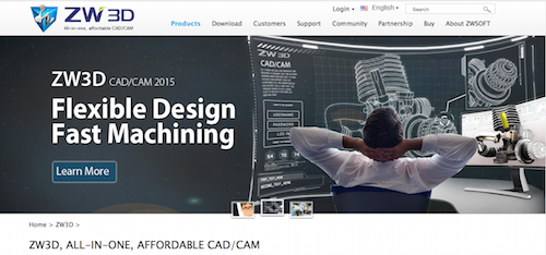
ZWSOFT is a well-knwon CAD/CAM solutions provider. Their ZW3D is an all-in-one CAD/CAM solution that is designed for the complete product design and development process. This engineering design tool features an easy-to-use 3D CAD module that greatly reduces design time.
Key Features:
5. MechDesigner
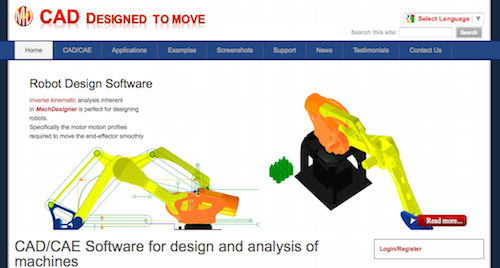
MechDesigner is an engineering design tool that was developed specifically for the design and analysis of machines and products that have moving parts, and for those parts to move the way you want them to move. With MechDesigner, you can ensure that your designs will move smoothly and with precision, even if your machine or product has complex motions, multiple interacting mechanisms, Cams, gears, or CAD designed parts.
Key Features:
6. PTC Creo
@PTC

PTC seeks to enable manufacturers to achieve product and service advantage in the age of the Internet of Things. Their award-winning 2D and 3D CAD software, PTC Creo, is a scalable suite of product design software that promises fast time to value. With PTC Creo, design engineering teams create, analyze, view, and leverage product designs utilizing 2D CAD, 3D CAD, parametric, and direct modeling.
Key Features:
7. BricsCAD
@bricsys
BricsCAD offers the familiar .dwg CAD features design engineers are accustomed to, but adds time-saving tools and 3D direct modeling at an affordable price. This powerful CAD platform “unifies advanced 2D design with the intelligence of 3D direct modeling,” for Windows, Linux, and Mac users.
Key Features:
@SiemensPLM
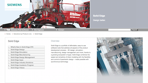
Solid Edge, a portfolio of affordable, easy-to-use software tools, addresses all aspects of the product design and development process for design engineers, including 3D design, simulation, manufacturing, design management, and more. With its synchronous technology, Solid Edge combines the speed and simplicity os direct modeling with the flexibility and control of parametric design.
Key Features:
9. Rhino
@bobmcneel

Rhino 5 is the world’s most versatile 3D modeler, available for Windows and Mac. With thousands of modeling and editing tools, Rhino is a complete engineering design tool that enables you to create, edit, analyze, document, render, animate, and translate NURBS curves, surfaces, and solids, point clouds, and polygon meshes without any limits on complexity, degree, or size beyond those of your hardware.
Key Features:
@SolidFaceCAD

SolidFace is a 2D/3D parametric historic constructive CAD modeler. SolidFace enables design engineers to accelerate their designs, increase productivity, and reduce cost with its 3D solid modeling that delivers true visualization and real testing prior to manufacturing.
Key Features:
@TopSolid
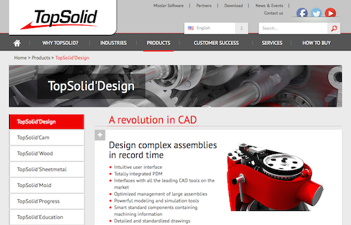
TopSolid seeks to help design engineers master the manufacturing process with CAD, CAM, ERP, and PDM software. Specifically, TopSolid Design offers “a revolution in CAD” so that you can “design complex assemblies in record time.”
Key Features:
12. Geomagic Design
@Geomagic

Geomagic, a leading provider of 3D software, helps design engineers create digital models of physical objects for reverse engineering, product design, inspection, and analysis. With Geomagic Design, design engineers get comprehensive 3D CAD tools for design, engineering, and preparation for manufacturing. Geomagic Design ensures rapid, accurate product design and development in an easy-to-use environment.
Key Features:
13. SpaceClaim 3D Modeling Software
@spaceclaim

SpaceClaim, a fast and innovative 3D direct modeler, helps design engineers solve geometry problems quickly. With SpaceClaim, you can work with 3D modeling software quickly and easily, anywhere in the workflow.
Key Features:
14. TurboCAD Designer
@imsidesign

TurboCAD Designer delivers easy and affordable 2D drafting and design at the beginner, intermediate, and advanced levels. Design engineers can complete all of their technical illustrations with TurboCAD Designer, which provides access to hundreds of 2D drawing, modifying, and dimensioning tools.
Key Features:
15. ANSYS DesignSpace
@ANSYS_Inc
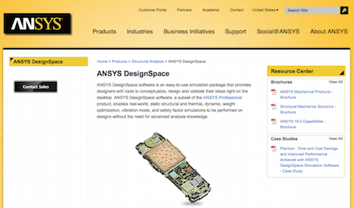
ANSYS, Inc. offers engineering simulation software, and ANSYS DesignSpace is the easy-to-use simulation tool that provides design engineers with the tools necessary for conceptualizing, designing, and validating their ideas right on their desktops. Even without advanced analysis knowledge, design engineers are able to perform real-world, static structural and thermal, dynamic, weight optimization, vibration mode, and safety factor simulations on designs when utilizing ANSYS DesignSpace.
Key Features:
16. Patran
@MSCSoftware
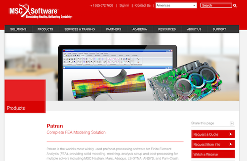
MSC Software provides simulation software for virtual product development. Patron is their complete Finite Element Analysis (FEA) modeling solution for design engineers that provides solid modeling, meshing, analysis setup, and post-processing for multiple solvers including MSC Nastran, Marc, Abacus, LS-DYNA, ANSYS, and Pam-Crash.
Key Features:
17. Simulia
@3DS_SIMULIA

3DS SIMULIA, powered by Dassault Systèmes’ 3DEXPERIENCE Platform, provides realistic simulation applications that enable design engineers “to explore the real-world behavior of product, nature, and life.” SIMULIA applications accelerate the process of evaluating the performance, reliability, and safety of materials and products before design engineers commit to physical prototypes.
Key Features:
18. COMSOL Multiphysics
@COMSOL_Inc
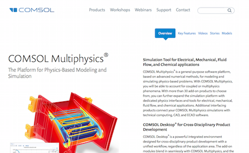
COMSOL Multiphysics is “the original multi physics simulation software.” COMSOL is a platform for physics-based modeling and simulation that serves as an engineering design tool. This general-purpose software platform is based on advanced numerical methods for modeling and simulating physics-based problems so that design engineers can account for coupled or multi physics phenomena.
Key Features:
19. ANSYS Fluent
@ANSYS_Inc

ANSYS Fluent software for design engineers contains the physical modeling capabilities needed to model flow, turbulence, heat transfer, and reactions for industrial applications. ANSYS Fluent is an engineering design software solution that includes special models so the software is capable of modeling in-cycle combustion, aeroacoustics, turbomachinery, and multiphase systems. ANSYS Fluent is considered an integral part of the design and optimization phases of global companies’ product development.
Key Features:
20. MapleSim
@maplesoft
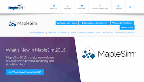
Maplesoft provides software for engineers, and MapleSim is their advanced physical modeling and simulation engineering design tool. Apply modern techniques to greatly reduce model design and development time, provide greater insight into system behavior, and produce fast, high-fidelity simulations with MapleSim.
Key Features:
21. The Engineering ToolBox
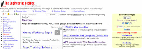
The Engineering Toolbox is an online tool for design engineers that provides resources, tools, and basic information. The tool adapts for smartphones, tablets, and desktops so that design engineers always have the optimized version of the toolbox available to them. Electrical, mechanical, and structural engineers will find The Engineering ToolBox useful as an engineering design tool.
Key Features:
22. Femap
@SiemensPLM

An advanced engineering simulation software program suitable for design engineers, Femap creates finite element analysis models of complex engineering products and systems and displays solution results. Femap virtually models components, assemblies, or systems and determines the behavioral response for a given operating environment.
Key Features:
23. Linear Technology Design Simulation and Device Models
@LinearTech
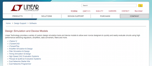
Linear Technology offers several custom design simulation tools and device models to allow design engineers to quickly and easily evaluate circuits using high-performance switching regulators, amplifiers, data converters, filters, and more. These engineering design tools are available online, free of charge, and provide design engineers with fast, reliable simulations and models.
Key Features:
24. KeyCreator Direct CAD
@KubotekUSA
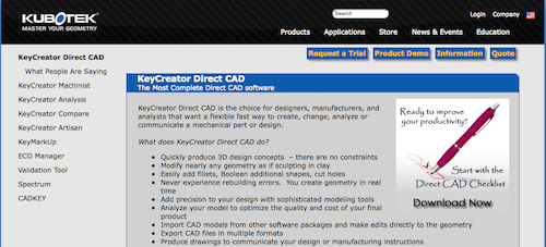
KeyCreator Direct CAD is a complete direct CAD software for design engineers who are looking for a flexible, quick way to create, change, analyze, or communicate a mechanical part or design. KeyCreator makes it possible to master your geometry and quickly produce 3D design concepts without constraints.
Key Features:
25. FreePCB
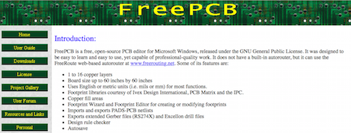
FreePCB, a free, open-source PCB editor for Windows, is capable of producing professional-quality work for design engineers. FreePCB is a design tool that helps design engineers quickly create PCBs of 1 to 16 copper layers.
Key Features:
26. Power Supply WebDesigner
@FairchildSemi
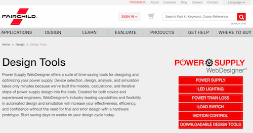
Fairchild is a global leader in power semiconductor and mobile technology. Their Power Supply WebDesigners is a suite of time-saving tools for designing and optimizing your power supply. This engineering design tool suite includes the models, calculations, and steps to make selecting, designing, analyzing, and simulating your power supply a much quicker process.
Key Features:
27. KOMPAS-3D
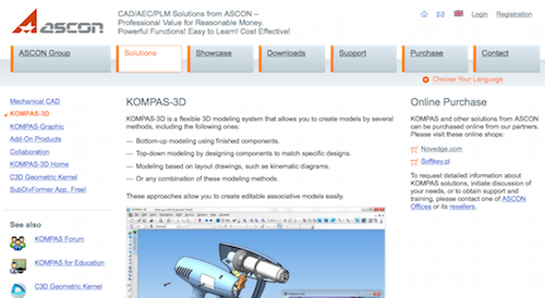
KOMPAS-3D, a flexible 3D modeling system, is an engineering design tool that allows design engineers to create models using several methods. Create editable associate models easily using KOMPAS-3D and its powerful functions that can manage projects with thousands of sub-assemblies, parts, and standard library products.
Key Features:
28. WEBENCH Design Center
@TXInstruments
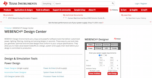
WEBENCH Design Center, from Texas Instruments, offers powerful online software tools that help design engineers generate and simulate designs that conform to unique specifications. Optimize your designs and make value-based tradeoffs at the design, system, or supply chain level before committing your design to production with WEBENCH Design Center.
Key Features:
29. TinyCAD
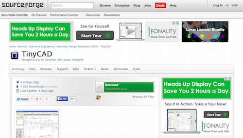
TinyCAD, an opens-ource program for drawing electrical circuit diagrams, or schematic drawings, is a handy engineering design tool that supports standard and custom symbol libraries. TinyCAD also supports PCB layout programs with several netlist formats and is capable of producing SPICE simulation netlists.
Key Features:
30. CircuitLab
@CircuitLab
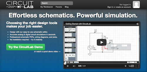
CircuitLab is an in-browsewr schematic editor and circuit simulator that helps design engineers save time designing and documenting their projects. CircuitLab’s professional-grade schematics, wiring diagrams, and precise simulations make it the perfect engineering design tool.
Key Features:
@DraftSight
DraftSight CAD Software allows design engineers to access existing DWG files and create new ones at an affordable price. DraftSight’s familiar user interface and ease of use make it a top CAD pick among design engineers. DraftSight CAD Software is available as a free download for students, hobbyists, and other individuals, in a professional pack for small and medium-sized companies, and in an enterprise pack for large corporations.
Key Features:
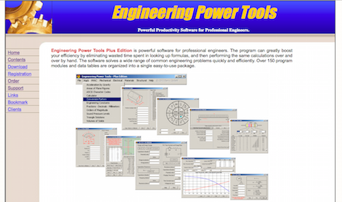
Engineering Power Tools Plus Edition is powerful software for professional engineers. Design engineers who use Engineering Power Tools increase their productivity and efficiency because they avoid looking up formulas and performing repeated calculations.
Key Features:
@IronCADTeam

IronCAD is a leading provider of innovative design collaboration solutions, which deliver productivity and design freedom. IronCAD offers INOVATE, a 3D design collaboration tool for design engineers that allows for creating, modifying, interrogating, and communicating 3D designs, from concept to production.
Key Features:
34. RecurDyn Professional
@FunctionBayGmbH

RecurDyn Professional is a CAE software solution for design engineers that consists of three modules: modeler, solver, and ProcessNet. With RecurDyn Professional, design engineers can test various conditions, even when they are difficult to repeat. This engineering design tool is also able to detect problems and product defects and solve them.
Key Features:
35. SOLIDWORKS Industrial Designer
@SOLIDWORKS

SOLIDWORKS Industrial Designer (SWID) is a concept design tool that helps design engineers quickly generate multiple industrial design concepts in response to a design brief. SWID includes unique tools for the rapid creation, manipulation, and modification of designs using both native and imported geometry. With SWID’s broad-based collaborative framework, design engineers accelerate their designs and reduce costs.
Key Features:
36. QCAD
@qcad_org

QCAD is a free, open-source 2D CAD program for Windows, Mac, and Linux. With QCAD, design engineers are able to create technical drawings for mechanical parts, schematics, and diagrams. QCAD’s intuitive interface and ease of use make it a top pick among design engineers.
Key Features:
37. Shark FX v9
@Punch_Software
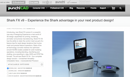
PunchCAD offers tools for engineering designs that require 2D or 3D rendering. Their Shark FX version 9 features new and powerful 3D design capabilities for printing, rendering, animation, and precise manufacturing. Shark FX V9 also helps design engineers with rapid design iterations involving mesh and precise feature operations, with its ability to retain the control mesh as part of a feature tree.
Key Features:
@CadSoftTech
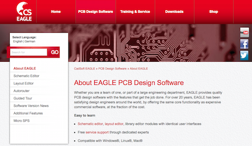
EAGLE PCB Design Software has been helping design engineers on a global scale for more than 20 years. An engineering design tool fit for a team of one or a large engineering department, EAGLE PCB Design Software offers the same core functions as expensive commercial software but at a fraction of the cost.
Key Features:
39. PCSCHEMATIC Automation
@PCSCHEMATIC
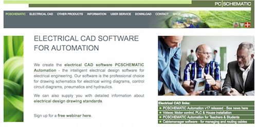
PCSCHEMATIC Automation is a top choice for electrical engineers looking for an intelligent electrical design software solution. This engineering design tool is a professional solution for drawing schematics for electrical wiring diagrams, control circuit diagrams, pneumatics, and hydraulics.
Key Features:
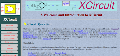
Tim Edwards created XCircuit, a program for drawing publishable-quality electrical circuit schematic diagrams and related figures, that is available as an online engineering design tool. XCircuit also produces circuit netlists through schematic capture and writes both hierarchical PostScript output and hierarchical SPICE netlists.
Key Features:
41. Autodesk Digital Prototyping
@autodesk

As an engineering design tool, Autodesk Digital Prototyping helps design engineers make great products by replacing siloed tools with integrated ones. Autodesk Digital Prototyping makes it possible for design engineers to streamline the entire product design and development process because they can explore their ideas before building them.
Key Features:
42. SALOME
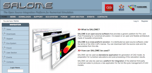
An open-source software that provides a generic platform for pre- and post-processing for numerical simulation, SALOME is an engineering design tool that is based on an open and flexible architecture made of reusable components. Design engineers use SALMOE both as a standalone application for generation of CAD models and as a platform for integration of the external third-party numerical codes to produce a new application for the full life-cycle management of CAD models.
Key Features:
43. GeckoCIRCUITS

GeckoCIRCUITS is a circuit simulator for modeling power electronics systems. This engineering design tool delivers fast circuit simulation capabilities, plus combines control modeling and thermal simulations.
Key Features:
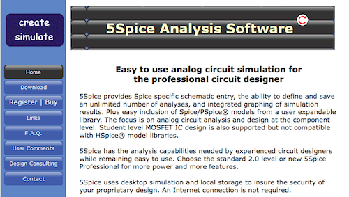
5Spice is an easy-to-use analog circuit simulator for professional circuit designers. This engineering design tool provides Spice-specific schematic entry, as well as the ability to define and save an unlimited number of analyses and integrated graphic of simulation results.
Key Features:
@Elecdes

Elecdes Design Suite (EDS) is an award-winning electrical design and instrumentation software suite. EDS is engineering design software that integrates with CAD software to extend design capabilities with electrical concepts, thereby allowing design engineers to think and work with “breakers, circuits, and terminal strips” rather than “circles, lines, and arcs.”
Key Features:
46. NX for Design
@SiemensPLM

NX for Design, an integrated product design solution, is an engineering design tool that streamlines and accelerates the product development process for engineers. Deliver innovative products in a collaborative environment using NX for Design.
Key Features:
47. Engineering Unit Converter

Professor S. Bhattacharjee of San Diego State University offers Engineering Unit Converter, a comprehensive engineering unit converter available for Android devices. This handy engineering design tool features an intuitive spinning wheel interface and helps design engineers convert units from anywhere, any time and has earned a 4.3 star rating from more than 2,370 Google Play reviewers.
Key Features:
48. TechCalc100 Engineering Software

Designers west publishes TechCalc100 engineering and scientific calculation software that helps design engineers rapidly complete calculations. The practical calculations provided by TechCalc100 are useful for mechanical, electrical, structural, and physics calculations, making this engineering scientific software by Designerswest a handy engineering design tool.
Key Features:
The Engineering Cookbook is a convenient reference guide for mechanical designers. This engineering design tool is an Android app that provides access to information frequently needed by mechanical designers, in the palm of their hands.
Key Features:
50. Electrical Engineering
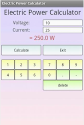
An Android app, Electrical Engineering is an engineering design tool that provides three tools in one: an electrical calculator, an electrical circuit calculator, and electrical formulas. The app also covers a broad range of subfields including electronics, power engineering, telecommunications, control systems, radio frequency engineering, and signal processing.
Key Features:
We at Pannam recognize all of the challenges and demands design engineers face, so we have compiled a list of the top engineering design tools, software, and apps in the hopes of making your job a little easier. Our top engineering design picks cover mechanical, electrical, and structural engineering design needs and include CAD programs, simulation tools, modeling tools, digital prototyping software, engineering calculation and conversion tools, pocket reference, and other solutions specifically for design engineering.

Please note, we have listed our top engineering design software, tools, and apps here, in no particular order.
1. Autodesk Product Design Suite
@autodesk

Autodesk is best known for its 3D design and engineering software and services. We like Autodesk Product Design Suite because it is a comprehensive 3D product design solution that offers everything design engineers need, from simulation, to collaboration, to visualization, to digital prototyping tools. Complete your entire engineering process with Autodesk Product Design Suite.
Key Features:
- Use 2D AutoCAD drawings as a base for inventor layouts
- Quickly and easily make product design changes
- Integrate electrical and mechanical design
- Get to market faster by reducing rework and reusing design data
- Reduce manufacturing costs by creating accurate design documentation and evaluating product manufacturability
- Product Design Suit Premium: $2,310 annual desktop subscription with basic support
- Monthly payments, perpetual licenses, and advanced support also are available – Contact for more pricing information
@MATLAB

A high-level language and interactive environment for numerical computation, visualization, and programming, MATLAB is an engineering design tool preferred by millions of engineers and scientists worldwide. With MATLAB, you can explore and visualize ideas and collaborate across disciplines to put your ideas into action.
Key Features:
- Numeric computation to use mathematical functions to solve science and engineering problems
- Core math functions use processor-optimized libraries to provide fast execution of vector and matrix calculations
- Explore, visualize, and model your data
- Share results as plots or complete reports
- Standard individual license: $2,150
- Group license: Contact for a quote
@3DSATIA

A Dassault Systèmes pioneer brand, CATIA is the world’s leading solution for product design and innovation. This engineering design tool is used by leading organizations and is applicable in multiple industries. With CATIA, design engineers have the ability to model products in the context of real-life behavior, allowing them to “design in the age of experience.”
Key Features:
- Social design environment accessible through powerful 3D dashboards that drive business intelligence, real-time concurrent design, and collaboration across all stakeholders
- Provides an instinctive 3D experience with world-class 3D modeling and simulation capabilities that optimize the effectiveness of each user
- Delivers an inclusive product development platform that easily integrates with existing processes and tools, to enable multiple disciplines to leverage powerful and integrated specialist applications across all phases of the product design and development process
4. ZW3D
@ZWSOFT

ZWSOFT is a well-knwon CAD/CAM solutions provider. Their ZW3D is an all-in-one CAD/CAM solution that is designed for the complete product design and development process. This engineering design tool features an easy-to-use 3D CAD module that greatly reduces design time.
Key Features:
- The fastest kernel for solid-surface hybrid modeling
- Make full use of existing drawings with powerful data exchange when product planning
- Multiple methods of verification to guarantee the quality of your design
- Enhance internal and external cooperation with sample making
- Available in several versions, including ZW3D Standard, ZW3D Professional, ZW3D Premium, ZW3D 2X Machining, ZW3D 3X Machining, ZW3D Lite, and ZW3D Student Version
5. MechDesigner

MechDesigner is an engineering design tool that was developed specifically for the design and analysis of machines and products that have moving parts, and for those parts to move the way you want them to move. With MechDesigner, you can ensure that your designs will move smoothly and with precision, even if your machine or product has complex motions, multiple interacting mechanisms, Cams, gears, or CAD designed parts.
Key Features:
- CAD/CAE software for design and analysis of machines, cams, mechanisms, and motions
- Design and build 3D machines with as many mechanisms as you need
- Create, edit, analyze, and view your interacting mechanisms in a 3D environment, plus add solids to the model
- Builds mechanisms with efficient kinematic equations that provide exact solutions
6. PTC Creo
@PTC

PTC seeks to enable manufacturers to achieve product and service advantage in the age of the Internet of Things. Their award-winning 2D and 3D CAD software, PTC Creo, is a scalable suite of product design software that promises fast time to value. With PTC Creo, design engineering teams create, analyze, view, and leverage product designs utilizing 2D CAD, 3D CAD, parametric, and direct modeling.
Key Features:
- A robust, scalable 3D product design toolset
- Greater power and more flexibility to help accelerate the product design and development process
- Unite Technology – work more effectively with data from multiple CAD sources and convert data when you need to, as you need to, to work from a single CAD platform
- Improved dedicated concept development toolset
7. BricsCAD
@bricsys

BricsCAD offers the familiar .dwg CAD features design engineers are accustomed to, but adds time-saving tools and 3D direct modeling at an affordable price. This powerful CAD platform “unifies advanced 2D design with the intelligence of 3D direct modeling,” for Windows, Linux, and Mac users.
Key Features:
- Clean, consistent user experience with a familiar interface
- Create 2D technical drawings quickly and accurately
- Performs 3D direct modeling with assemblies in the standard .dwg format
- Speed workflow with the context-sensitive Quad cursor
- Collaborate and annotate projects in the cloud
- BricsCAD Classic: $520 – Powerful CAD functions, 2D constraints solving, full support of LISP, and Chapoo connectivity
- BricsCAD Pro: $650 – All Classic edition features, plus direct 3D modeling, rendering, materials, and lighting, 3D constraints solving, and more
- BricsCAD Platinum: $990 – All Pro edition features, plus 3D constraint creation, design intent recognition, assembly modeling, and more
@SiemensPLM

Solid Edge, a portfolio of affordable, easy-to-use software tools, addresses all aspects of the product design and development process for design engineers, including 3D design, simulation, manufacturing, design management, and more. With its synchronous technology, Solid Edge combines the speed and simplicity os direct modeling with the flexibility and control of parametric design.
Key Features:
- A growing ecosystem of apps and software tools that include Solid Edge Design, Solid Edge Simulation, Solid Edge Manufacturing, Solid Edge Design Management, and more
- Exceptional tools for creating and managing 3D digital prototypes
- Guide your projects toward an error-free, accurate design solution
- Merges design management capabilities with the CAD tools design engineers use every day
9. Rhino
@bobmcneel

Rhino 5 is the world’s most versatile 3D modeler, available for Windows and Mac. With thousands of modeling and editing tools, Rhino is a complete engineering design tool that enables you to create, edit, analyze, document, render, animate, and translate NURBS curves, surfaces, and solids, point clouds, and polygon meshes without any limits on complexity, degree, or size beyond those of your hardware.
Key Features:
- Uninhibited free-form 3D modeling tools that enable design engineers to model any shape imaginable
- Compatible with all other design, drafting, CAM, engineering, analysis, rendering, animation, and illustration software
- Read and repair meshes and extremely challenging IGES files
- Full Rhino 5 for Windows: $995 – single user
- Full Rhino 5 for Mac: $495 – single user
@SolidFaceCAD

SolidFace is a 2D/3D parametric historic constructive CAD modeler. SolidFace enables design engineers to accelerate their designs, increase productivity, and reduce cost with its 3D solid modeling that delivers true visualization and real testing prior to manufacturing.
Key Features:
- Speeds design development and detailing
- Improves visualization and communication
- Eliminates design interference issues
- Checks design functionality and performance, without the need for physical prototypes
- Built-in 3D direct modeling module
- Built-in 2D/3D movement simulation module
- 2D/3D Pro Lifetime License: Starting at $999
- 2D/3D Monthly License: $59.99
- 2D/3D Pro Students Version: $129
- 2D Drawing Lifetime License: $399
@TopSolid

TopSolid seeks to help design engineers master the manufacturing process with CAD, CAM, ERP, and PDM software. Specifically, TopSolid Design offers “a revolution in CAD” so that you can “design complex assemblies in record time.”
Key Features:
- Intuitive user interface
- Totally integrated PDM
- Interfaces with all the leading CAD tools on the market
- Optimized management of large assemblies
- Powerful modeling and simulation tools
- Smart standard components containing machining information
- Detailed and standardized drawings
12. Geomagic Design
@Geomagic

Geomagic, a leading provider of 3D software, helps design engineers create digital models of physical objects for reverse engineering, product design, inspection, and analysis. With Geomagic Design, design engineers get comprehensive 3D CAD tools for design, engineering, and preparation for manufacturing. Geomagic Design ensures rapid, accurate product design and development in an easy-to-use environment.
Key Features:
- 3D model creation
- 3D printability tools
- Create flexible designs that can be reused and customized using global parameters
- Direct editing toolset
- Photorealistic rendering
13. SpaceClaim 3D Modeling Software
@spaceclaim

SpaceClaim, a fast and innovative 3D direct modeler, helps design engineers solve geometry problems quickly. With SpaceClaim, you can work with 3D modeling software quickly and easily, anywhere in the workflow.
Key Features:
- Edit, repair, and create any geometry, without worrying about where the file comes from
- Increase productivity by removing the CAD bottleneck in your workflow
- Manipulate geometry faster and more intuitively so you can spend less time with the geometry and more time on manufacturing, analyzing, and concept modeling
14. TurboCAD Designer
@imsidesign

TurboCAD Designer delivers easy and affordable 2D drafting and design at the beginner, intermediate, and advanced levels. Design engineers can complete all of their technical illustrations with TurboCAD Designer, which provides access to hundreds of 2D drawing, modifying, and dimensioning tools.
Key Features:
- Share your work in over 20 popular file formats, including the latest AutoCAD DWG/DXF
- Use with snaps and drawing aids to speed design
- Easily import existing designs or share your work with others
- A complete set of 2D drafting and detailing tools
- Annotation tools
15. ANSYS DesignSpace
@ANSYS_Inc

ANSYS, Inc. offers engineering simulation software, and ANSYS DesignSpace is the easy-to-use simulation tool that provides design engineers with the tools necessary for conceptualizing, designing, and validating their ideas right on their desktops. Even without advanced analysis knowledge, design engineers are able to perform real-world, static structural and thermal, dynamic, weight optimization, vibration mode, and safety factor simulations on designs when utilizing ANSYS DesignSpace.
Key Features:
- Auto contact detection makes it easy to work with large assembly models
- Superior CAD interface and robust meshing
- Advanced numerical methods for nonlinear problems
- Powerful solver capabilities
- Advanced post-processing
- Reporting
16. Patran
@MSCSoftware

MSC Software provides simulation software for virtual product development. Patron is their complete Finite Element Analysis (FEA) modeling solution for design engineers that provides solid modeling, meshing, analysis setup, and post-processing for multiple solvers including MSC Nastran, Marc, Abacus, LS-DYNA, ANSYS, and Pam-Crash.
Key Features:
- Rich set of tools that streamlines the creation of analysis-ready models for linear, nonlinear, explicit dynamics, thermal, and other finite element solutions
- Easily creates meshes on surfaces and solids using fully-automated meshing routines, manual methods, or a combination of the two
- Built-in loads, boundary conditions, and analysis setup for most popular FE solvers
17. Simulia
@3DS_SIMULIA

3DS SIMULIA, powered by Dassault Systèmes’ 3DEXPERIENCE Platform, provides realistic simulation applications that enable design engineers “to explore the real-world behavior of product, nature, and life.” SIMULIA applications accelerate the process of evaluating the performance, reliability, and safety of materials and products before design engineers commit to physical prototypes.
Key Features:
- Multiphysics simulation
- Modeling and visualization
- Design simulation
- Design optimization
18. COMSOL Multiphysics
@COMSOL_Inc

COMSOL Multiphysics is “the original multi physics simulation software.” COMSOL is a platform for physics-based modeling and simulation that serves as an engineering design tool. This general-purpose software platform is based on advanced numerical methods for modeling and simulating physics-based problems so that design engineers can account for coupled or multi physics phenomena.
Key Features:
- More than 30 add-on products to choose from, to further expand the simulation platform
- Dedicated physics interfaces and tools for electrical, mechanical, fluid flow, and chemical applications
- Additional interfacing products connect COMSOL Multiphysics simulations with technical computing, CAD, and ECAD software
19. ANSYS Fluent
@ANSYS_Inc

ANSYS Fluent software for design engineers contains the physical modeling capabilities needed to model flow, turbulence, heat transfer, and reactions for industrial applications. ANSYS Fluent is an engineering design software solution that includes special models so the software is capable of modeling in-cycle combustion, aeroacoustics, turbomachinery, and multiphase systems. ANSYS Fluent is considered an integral part of the design and optimization phases of global companies’ product development.
Key Features:
- Advanced solver technology for fast, accurate CFD results, flexible moving and deforming meshes, and superior parallel scalability
- User-defined functions allow for implementing new user models and extensively customizing existing ones
- Easily pause a calculation, examine results with integrated post-processing, change any setting, and then continue the calculation within a single application, thanks to ANSYS Fluent’s interactive solver setup, solution, and post-processing capabilities
20. MapleSim
@maplesoft

Maplesoft provides software for engineers, and MapleSim is their advanced physical modeling and simulation engineering design tool. Apply modern techniques to greatly reduce model design and development time, provide greater insight into system behavior, and produce fast, high-fidelity simulations with MapleSim.
Key Features:
- Refine and optimize designs with a powerful, open analysis environment
- Develop high-fidelity system-level models significantly faster
- Investigate your models, create and manage libraries of custom components, and use your models with other simulation programs
21. The Engineering ToolBox

The Engineering Toolbox is an online tool for design engineers that provides resources, tools, and basic information. The tool adapts for smartphones, tablets, and desktops so that design engineers always have the optimized version of the toolbox available to them. Electrical, mechanical, and structural engineers will find The Engineering ToolBox useful as an engineering design tool.
Key Features:
- Charts and conversions
- Capacitor and connection notes
- Diagram templates
22. Femap
@SiemensPLM

An advanced engineering simulation software program suitable for design engineers, Femap creates finite element analysis models of complex engineering products and systems and displays solution results. Femap virtually models components, assemblies, or systems and determines the behavioral response for a given operating environment.
Key Features:
- Predict and improve product performance and reliability
- Reduce physical prototyping and testing time and cost
- Evaluate various designs and materials
- Optimize designs and reduce material usage
23. Linear Technology Design Simulation and Device Models
@LinearTech

Linear Technology offers several custom design simulation tools and device models to allow design engineers to quickly and easily evaluate circuits using high-performance switching regulators, amplifiers, data converters, filters, and more. These engineering design tools are available online, free of charge, and provide design engineers with fast, reliable simulations and models.
Key Features:
- LTspice IV, available for Windows and Mac OS X, is a high performance SPICE simulator, schematic capture, and waveform viewer
- LTpowerCAD II is a complete power supply design tool program
- LTpowerPlay is a Windows-based development environment that supports a variety of tasks and can be used in offline mode
24. KeyCreator Direct CAD
@KubotekUSA

KeyCreator Direct CAD is a complete direct CAD software for design engineers who are looking for a flexible, quick way to create, change, analyze, or communicate a mechanical part or design. KeyCreator makes it possible to master your geometry and quickly produce 3D design concepts without constraints.
Key Features:
- Modify nearly any geometry as easily as if you were sculpting clay
- Easily add fillets, Boolean additional shapes, and cut holes
- Create geometry in real time and eliminate rebuilding errors
- Add precision to your design with sophisticated modeling tools
25. FreePCB

FreePCB, a free, open-source PCB editor for Windows, is capable of producing professional-quality work for design engineers. FreePCB is a design tool that helps design engineers quickly create PCBs of 1 to 16 copper layers.
Key Features:
- Board size up to 60 inches by 60 inches
- Uses English or metric units for most functions
- Design rule checker
- Autosave
- Exports extended gerber files and Excellon drill files
26. Power Supply WebDesigner
@FairchildSemi

Fairchild is a global leader in power semiconductor and mobile technology. Their Power Supply WebDesigners is a suite of time-saving tools for designing and optimizing your power supply. This engineering design tool suite includes the models, calculations, and steps to make selecting, designing, analyzing, and simulating your power supply a much quicker process.
Key Features:
- Created for novice and experienced design engineers
- Industry-leading capabilities and flexibility in automated design and simulation
- Eliminate the need for trial-and-error design with a hardware prototype
- Provides complete converter designs to cover isolated or non-isolated AC or DC input configurations
27. KOMPAS-3D

KOMPAS-3D, a flexible 3D modeling system, is an engineering design tool that allows design engineers to create models using several methods. Create editable associate models easily using KOMPAS-3D and its powerful functions that can manage projects with thousands of sub-assemblies, parts, and standard library products.
Key Features:
- Bottom-up modeling using finished components
- Top-down modeling by designing components to match specific designs
- Modeling based on layout drawings, such as kinematic diagrams
- Supports all the capabilities of 3D solids and surface modeling, including intuitive creation of new geometry and importing and manipulation of surfaces, associative settings for element parameters, flexible parts and assembly editing, including characteristic points, and much more
28. WEBENCH Design Center
@TXInstruments

WEBENCH Design Center, from Texas Instruments, offers powerful online software tools that help design engineers generate and simulate designs that conform to unique specifications. Optimize your designs and make value-based tradeoffs at the design, system, or supply chain level before committing your design to production with WEBENCH Design Center.
Key Features:
- Power Designer (single supply)
- Automotive Power Designer
- Interface Designer
29. TinyCAD

TinyCAD, an opens-ource program for drawing electrical circuit diagrams, or schematic drawings, is a handy engineering design tool that supports standard and custom symbol libraries. TinyCAD also supports PCB layout programs with several netlist formats and is capable of producing SPICE simulation netlists.
Key Features:
- Flat or hierarchical schematic entry
- Many popular PCB layout compatible netlist formats
- Convenient support for embedding graphical images in drawings
30. CircuitLab
@CircuitLab

CircuitLab is an in-browsewr schematic editor and circuit simulator that helps design engineers save time designing and documenting their projects. CircuitLab’s professional-grade schematics, wiring diagrams, and precise simulations make it the perfect engineering design tool.
Key Features:
- Powerful, easy-to-use software for electronics designers and engineers
- Build schematics faster with the unique, intelligent Smart Wires technology for connecting terminals and rearranging components
- Presentation-quality schematics
- Rapid symbol creation
- Powerful plotting engine
- Behavioral sources and expressions
- CircuitLab Pro: $399/year or $39/month
- CircuitLab Platinum: $999/year or $100/month – Easily access new features and get CircuitLab Platinum Support
@DraftSight

DraftSight CAD Software allows design engineers to access existing DWG files and create new ones at an affordable price. DraftSight’s familiar user interface and ease of use make it a top CAD pick among design engineers. DraftSight CAD Software is available as a free download for students, hobbyists, and other individuals, in a professional pack for small and medium-sized companies, and in an enterprise pack for large corporations.
Key Features:
- CAD software with powerful, time-saving functionalities
- Includes industry standard content that you can add to documents with ease
- Enables batch printing to print multiple files without opening them
- Read and write support for DWG/DXF files
- Save DWG/DXF files back to previous versions
- DraftSight FREE – For students, hobbyists, and other individuals
- DraftSight Professional: $299.00/yearly subscription – After 12 months, a yearly fee of $99 is due starting with the next billing cycle
- DraftSight Enterprise: Contact for a quote

Engineering Power Tools Plus Edition is powerful software for professional engineers. Design engineers who use Engineering Power Tools increase their productivity and efficiency because they avoid looking up formulas and performing repeated calculations.
Key Features:
- Solves a wide range of common engineering problems quickly and efficiently
- Over 150 program modules and data tables, organized into a single package
- Modules for math, HVAC, mechanical, electrical, materials, and structural needs
- Engineering Power Tools Plus Edition
- Single-user license: $49.95
- Limited site license: $149.95
- Engineering Power Tools Standard Edition
- Single-user license: $24.95
- Limited site license: $99.95
@IronCADTeam

IronCAD is a leading provider of innovative design collaboration solutions, which deliver productivity and design freedom. IronCAD offers INOVATE, a 3D design collaboration tool for design engineers that allows for creating, modifying, interrogating, and communicating 3D designs, from concept to production.
Key Features:
- Drag-and-drop 3D environment
- Powerful, high-end visualization and animation technologies that make the entire design process faster, more productive, and easier to understand
- Includes CAXA EDM, an integrated and fully functional EDM solution to manage CAD and related engineering project data, both internally and externally across the internet
34. RecurDyn Professional
@FunctionBayGmbH

RecurDyn Professional is a CAE software solution for design engineers that consists of three modules: modeler, solver, and ProcessNet. With RecurDyn Professional, design engineers can test various conditions, even when they are difficult to repeat. This engineering design tool is also able to detect problems and product defects and solve them.
Key Features:
- RecurDyn Modeler is a pre-processor that creates analysis models
- RecurDyn Solver performs fast analysis with the optimized integrator after constructing the equation of motion
- Three types of contact: general contact, analytical contact, and toolkit contact
- Separates subsystems from complex systems and analyzes each subsystem
35. SOLIDWORKS Industrial Designer
@SOLIDWORKS

SOLIDWORKS Industrial Designer (SWID) is a concept design tool that helps design engineers quickly generate multiple industrial design concepts in response to a design brief. SWID includes unique tools for the rapid creation, manipulation, and modification of designs using both native and imported geometry. With SWID’s broad-based collaborative framework, design engineers accelerate their designs and reduce costs.
Key Features:
- Capture your ideas digitally, quickly create 3D concept models, get feedback from stakeholders, and easily manage multiple concepts before committing engineering time to building a prototype
- Combines subdivision surface modeling and parametric modeling, resulting in a flexible, instinctive solution
- Include Platform Contributor to easily save information in a safe, secure environment
- Includes intuitive freehand sketching, simplified design evolution, realistic rendering, and more
36. QCAD
@qcad_org

QCAD is a free, open-source 2D CAD program for Windows, Mac, and Linux. With QCAD, design engineers are able to create technical drawings for mechanical parts, schematics, and diagrams. QCAD’s intuitive interface and ease of use make it a top pick among design engineers.
Key Features:
- Layers
- Blocks (grouping)
- 35 CAD fonts included
- Over 20 modification tools
- Printing to scale
- DXF and DWG input and output
- Part library with more than 4,800 CAD parts
37. Shark FX v9
@Punch_Software

PunchCAD offers tools for engineering designs that require 2D or 3D rendering. Their Shark FX version 9 features new and powerful 3D design capabilities for printing, rendering, animation, and precise manufacturing. Shark FX V9 also helps design engineers with rapid design iterations involving mesh and precise feature operations, with its ability to retain the control mesh as part of a feature tree.
Key Features:
- State of the art technology converts meshes into optimized smooth NURB models suitable for solid modeling operations
- Exports to DWG, IGES, and STEP file formats
- Versatile, precise blending, chamfering, and shelling
- Mac download: $2,295
- Windows download: $2,295
- USB Flash Drive: $2,305
- DVD in Sleeve – Mac/Windows: $2,295
@CadSoftTech

EAGLE PCB Design Software has been helping design engineers on a global scale for more than 20 years. An engineering design tool fit for a team of one or a large engineering department, EAGLE PCB Design Software offers the same core functions as expensive commercial software but at a fraction of the cost.
Key Features:
- Schematic editor, layout editor, and library editor modules with identical user interfaces
- Free service support through dedicated experts
- Compatible with Linux, Windows, and Mac
- Flexible ULPs enable custom features, including individual instruction sequences, simulation, data export, and import
39. PCSCHEMATIC Automation
@PCSCHEMATIC

PCSCHEMATIC Automation is a top choice for electrical engineers looking for an intelligent electrical design software solution. This engineering design tool is a professional solution for drawing schematics for electrical wiring diagrams, control circuit diagrams, pneumatics, and hydraulics.
Key Features:
- An advanced electrical CAD solution for automation, installation, pneumatics, and hydraulics
- Easily maintain an overview of your electrical designs
- Focus on the electrical design while the program handles the practical side
- Provides a comprehensive series of functions designed for electrical projects and supports international electrical design drawing standards
- PCSCHEMATIC Automation – Floating network license: €3.220,00
- PCSCHEMATIC Automation – Stand-alone license: €2.740,00
- PCSCHEMATIC Automation Smart 40: €1.959,00
- PCSCHEMATIC Automation Smart 20: €1.365,00
- PCSCHEMATIC Automation Flex 350: €1.365,00
- PCSCHEMATIC Automation Flex 150: €890,00

Tim Edwards created XCircuit, a program for drawing publishable-quality electrical circuit schematic diagrams and related figures, that is available as an online engineering design tool. XCircuit also produces circuit netlists through schematic capture and writes both hierarchical PostScript output and hierarchical SPICE netlists.
Key Features:
- Saves circuit components in libraries that are fully editable
- Maintains flexibility in style without compromising the power of schematic capture
- Serves as an excellent electronic design automation tool
41. Autodesk Digital Prototyping
@autodesk

As an engineering design tool, Autodesk Digital Prototyping helps design engineers make great products by replacing siloed tools with integrated ones. Autodesk Digital Prototyping makes it possible for design engineers to streamline the entire product design and development process because they can explore their ideas before building them.
Key Features:
- Gather design data from all phases of the process into a single digital model
- Validate the design data against product requirements and reference it as you build deliverables for release
- Implement design software that addresses your specific needs, including collaboration and communication needs
- Create sketches and 3D concept models
- Design, visualize, and simulate products before releasing them to manufacturing
42. SALOME

An open-source software that provides a generic platform for pre- and post-processing for numerical simulation, SALOME is an engineering design tool that is based on an open and flexible architecture made of reusable components. Design engineers use SALMOE both as a standalone application for generation of CAD models and as a platform for integration of the external third-party numerical codes to produce a new application for the full life-cycle management of CAD models.
Key Features:
- Supports interoperability between CAD modeling and computation software (CAD-CAE link)
- Easily integrate new components into heterogeneous systems for numerical computation
- Create and modify, import and export, and repair and clean CAD models
- Mesh CAD models, edit mesh, check mesh quality, and import and export mesh
- Handle physical properties and quantities attached to geometrical items
43. GeckoCIRCUITS

GeckoCIRCUITS is a circuit simulator for modeling power electronics systems. This engineering design tool delivers fast circuit simulation capabilities, plus combines control modeling and thermal simulations.
Key Features:
- An easy-to-use software package
- Extremely high simulation speed
- Open interface
- May be integrated into MATLAB or other programming environments
- Single seat: €1980/year
- Dongle: €2480/year
- Universities: €540/year

5Spice is an easy-to-use analog circuit simulator for professional circuit designers. This engineering design tool provides Spice-specific schematic entry, as well as the ability to define and save an unlimited number of analyses and integrated graphic of simulation results.
Key Features:
- Easy inclusion of Spice/PSpice models from a user-expandable library
- Uses desktop simulation and local storage to ensure the security of your proprietary designs
- Does not require an internet connection
- Behavioral modeling
- Multi-page schematic
- User-defined parameters to set static and swept component values
- Tool to make schematic into Spice subcircuit
- 5Spice Analysis
- Single copy: $210
- 3 or more copies: $190
- 5Spice Professional
- Single copy: $319
- 3 or more copies: $277
@Elecdes

Elecdes Design Suite (EDS) is an award-winning electrical design and instrumentation software suite. EDS is engineering design software that integrates with CAD software to extend design capabilities with electrical concepts, thereby allowing design engineers to think and work with “breakers, circuits, and terminal strips” rather than “circles, lines, and arcs.”
Key Features:
- Instrumentation, panel, and electrical CAD design software
- Data-centric, allowing users to reduce the amount of work required for repetitive tasks
- Global editing of electrical CAD entities, advanced reporting, and database-driven instrument management
46. NX for Design
@SiemensPLM

NX for Design, an integrated product design solution, is an engineering design tool that streamlines and accelerates the product development process for engineers. Deliver innovative products in a collaborative environment using NX for Design.
Key Features:
- Offers the highest level of integration between development disciplines in an open, collaborative environment
- Leading-edge 3D product design solution
- Flexible, robust computer-aided design and styling software that accelerates product engineering by providing fast concept design and modeling
47. Engineering Unit Converter

Professor S. Bhattacharjee of San Diego State University offers Engineering Unit Converter, a comprehensive engineering unit converter available for Android devices. This handy engineering design tool features an intuitive spinning wheel interface and helps design engineers convert units from anywhere, any time and has earned a 4.3 star rating from more than 2,370 Google Play reviewers.
Key Features:
- Choose a category such as length, energy, entropy, electrical charge, or others from a list and spin the wheels to select a “From Unit” and a “To Unit”
- Change the input value, sort units, or swap as needed
- Additional information about measurements is displayed when you press the Help button
- Does not require internet access
48. TechCalc100 Engineering Software

Designers west publishes TechCalc100 engineering and scientific calculation software that helps design engineers rapidly complete calculations. The practical calculations provided by TechCalc100 are useful for mechanical, electrical, structural, and physics calculations, making this engineering scientific software by Designerswest a handy engineering design tool.
Key Features:
- Includes 100 practical calculations for structural, electrical, mechanical, and physics applications
- Appropriate for use in all aspects of engineering design
- Written in English units
- Requires Microsoft Excel
- Single user: $49.95
- 2-5 users: $79.00
- 6-19 users: $149
- 20-49 users: $199
- 50-100 users: $299

The Engineering Cookbook is a convenient reference guide for mechanical designers. This engineering design tool is an Android app that provides access to information frequently needed by mechanical designers, in the palm of their hands.
Key Features:
- Heating and cooling load estimation
- Sound and vibration guidelines
- Ventilation rates for indoor air quality
- Design formulas and conversion factors
50. Electrical Engineering

An Android app, Electrical Engineering is an engineering design tool that provides three tools in one: an electrical calculator, an electrical circuit calculator, and electrical formulas. The app also covers a broad range of subfields including electronics, power engineering, telecommunications, control systems, radio frequency engineering, and signal processing.
Key Features:
- Calculate the most important electrical sizes and the electrical power, electrical resistance, electrical charge, electrical work, and electrical current
- Calculate the current in parallel circuits, the voltage in series circuits, and the resistance in parallel and series circuits
- See formulas for electrical power, electrical resistance, electrical work, electrical current, and electrical charge
- Calculate the stored energy in a capacitor, the inductance and the capacitance, and the output voltage of a voltage divider

