Showing posts with label LEVEL. Show all posts

Sunday 11 November 2018

QUESTION: DESCRIBE THE SOURCES OF ERROR IN LEVELING


            DESCRIBE THE SOURCES OF ERROR IN LEVELING
Image result for reciprocal levelling

            Many sources of error exist in levelling and the most commonly met in practice are discussed. Firstly, one of the sources of error is errors in the equipment which is collimation error. This can be a serious source of error in levelling if the sight lengths from one instrument position are not equal, since the collimation error proportional to the difference in sight length. The line of collimation should be parallel to the line of sights. 
Image result for reciprocal levelling
Hence, in all types of levelling, sights should kept equal, particularly back sights and fore sights. Before using any level it is advisable to carry out a two-peg to ensure that the collimation error is as 
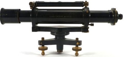
small as possible. Other than that, compensator not working. The function of compensator is to deviate the horizontal ray of light at the optical center of the object lens through the center of the cross hairs. This ensure that line of sight viewed through the telescope is horizontal.  
Image result for reciprocal levelling
If the reading changes to a different position each time the footscrew is moved or thr instrument tapped, the compensator is not working properly and the instrument should be returned to the manufacturer 
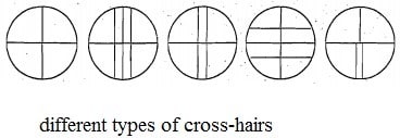
for repair. Parallax  also one of error in the equipment. Parallax must be eliminated before any readings are taken. Parallax is occur when the image of the distance point or object and focal plane are not fall exactly in the plane of the diaphragm. 
Image result for reciprocal levelling
To eliminate parallax, the eyepiece is first adjusted until the cross hairs appear in sharp focus. Then, defects on the staff  which is the incorrect graduation staff cause the zero error. This does not effect height differences if the same staff is used for all the levelling but introduces errors if to staves used for the same series of levels. When using a multisection staff, it is important to unsure that it is properly extended by examining the graduations on either side of each joint. The stability of tripods should also be checked before any fieldwork commences .
Image result for reciprocal levelling 
                     Secondly, field errors 
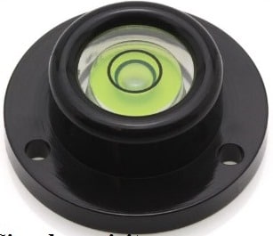
also source of error. The example of field errors is staff not vertical, failure to hold the staff vertical will result in incorrect readings. The staff is held vertical with the aid of a circular bubble. At frequent intervals the circular bubble should checked against plumb line and adjusted if necessary. Another example of field errors is unstable ground. When the instrument is set up on soft ground and bituminous surfaces on hot days, an effect often overlooked is that the tripod legs may sink into the ground or rise slightly while readings are being taken.This alters the height collimation and therefore advisable to choose firm ground on which to set up the level. 

After that, handling the instrument and tripod as well as vertical displacement, the HPC may be altered for any set-up if the tripod is held or leant against. When levelling, avoid contact with the tripod and only use the level by light contact through 
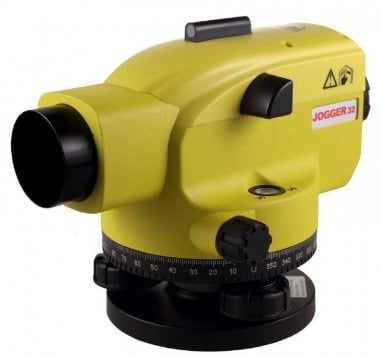
the fingertips. Then, instrument not level is also the field errors. For automatic levels this source of error is unusual but, for tilting level in which the tilting screw has to be adjusted for each reading, this is common mistake. The best solution is to ensure the main bubble is centralised before and after reading.
 Image result for reciprocal levelling
                 Thirdly, source of error is the effects of curvature and refraction on levelling. The effect of atmospheric on the line of sight is to bend it towards the Earth’s surface causing staff readings to be too low. This is variable effect depending on atmospheric condition but for ordinary work refraction is assumed to have value 1/7 that of curvature bit is of opposite sign. The combined and refraction correction is c + r = 0.0673 D². If longer sight lengths must be used, it is worth remembering that the effects of curvature and refraction will cancel if the sight length are equal. But, curvature and refraction cannot always be ignored when calculating heights using theodolite methods.
 Image result for reciprocal levelling
                  Lastly, source of error is reading and booking error and also weather conditions. Source of reading error is the sighting the staff over too long a distance, when it becomes impossible to take accurate readings. It is , therefore, recommended that sighting distances should be limited to 50m but, where absolutely unavoidable, this may be increased to maximum of 100m. For weather conditions, when it windy will cause the level to vibrate and give rise to difficulties in holding the staff steady. In hot weather, the effect of refraction are serious and produce a shimmering effect near ground level. The reading cannot be read accurately.


QUESTION : EXPLAIN BASIC RULES IN PRACTICE WHEN CONDUCTING A LEVELING


1.     EXPLAIN BASIC RULES IN PRACTICE WHEN CONDUCTING A LEVELING
    Image result for reciprocal levelling
                Levelling is the process of measuring the difference in elevation between two or more points. In engineering surveying, levelling has many application and is used at all stages in construction projects from the initial site survey through the final setting out. In practice, it is possible to measure heights to better than a few millimeters when levelling  this precision  is more than adequate for height measurement on the majority of civil engineering project.
Image result for reciprocal levelling
The basic rules in practice when conducting a levelling fieldwork should be adhered to if many of the sources of error are to be avoided. Levelling should always start and finish  at points of known reduced level so that misclosures can be detected. When only one bench mark is available, levelling lines must be run in loops starting and finishing at the bench mark. 
Image result for reciprocal levelling
Where possible, all sights length should below 50m. The staff must be held vertically by suitable use of a circular bubble or by rocking the staff and notong the minimum reading. Backsight and fortsight length should be equal for each instrument position. For engineering application, many intermediate sight readings may be taken from each set- up. Under this circumstances it is important that the level has no more than a small collimation error. 
Image result for reciprocal levelling
Reading should book immediately after they are observed and important readings, particularly at change points, should be checked. The rise and fall method of reduction should used when heighting reference or change  points and the HPR method ( height of collimation) should be used for contouring , sectioning and setting out applications.
Image result for reciprocal levelling

Monday 30 October 2017

Different Types of Levels Used for Leveling in Surveying

Different Types of Levels Used for Leveling in Surveying


There are various types of levels for leveling in surveying. The process of measuring vertical distances in surveying is called leveling.


To perform leveling, we need some level instruments to focus or to read the object. Nowadays, the technology also introduced in surveying and so many easy measuring instruments are designed. Here we discuss about the different levels used in leveling.

Types of Levels Used in Leveling

Following are the types of different levels used for leveling in surveying:

Dumpy level


Y level


Cushing’s level


Tilting level


Cooke’s reversible level


Automatic level


Dumpy Level

Dumpy level is the most commonly used instrument in leveling. In this level the telescope is restricted against movement in its horizontal plane and telescope is fixed to its support. A bubble tube is provided on the top of the telescope.

But however, the leveling head can be rotated in horizontal plane with the telescope. The telescope is internal focusing telescope is a metal tube contains four main parts as given below.

Objective lens


Negative lens


Diaphragm


Eye-piece


Objective Lens

Objective lens should be made as the combination of crown glass and flint glass. Because of this some defects like spherical aberration and chromatic aberration can be eliminated. A thin layer coating which has smaller refractive index than glass is provided on the objective lens to reduce the loss due to reflection.

Negative Lens

Negative lens located co axial to the objective lens. So, the optical axis for both lenses is same.

Diaphragm

Diaphragm is fitted inside the main tube which contains cross hairs (vertical and horizontal) and these are adjusted by capstan headed screws. The cross hairs are made of dark metal as filament wires which are inserted in diaphragm ring in exact position. For stadia leveling purposes, extra two horizontal cross hairs are provided above and below the horizontal wire.

Eyepiece

Eyepiece lens enable the ability to sight the object together with cross hairs. The image seen through eye piece is magnified and inverted. Some eyepieces erect the image into normal view and those are called as erecting eyepieces.

Y Level

Y level or Wye-level consists y-shaped frames which supports the telescope. Telescope cane be removed from the y-shaped supports by releasing clamp screws provided. These y-shaped frames are arranged to vertical spindle which helps to cause the rotation of telescope.

Compared to dumpy level, adjustments can be rapidly tested in y- level. But, there may be a chance of frictional wear of open parts of level.

Cushing’s Level

In case of Cushing’s level, the telescope is restricted against rotation in its longitudinal axis and it is non-removable. But, the object end and eye piece end can be interchangeable and reversible.

Tilting Level

Tilting level consist a telescope which enabled for the horizontal rotation as well as rotation about 4 degree in its vertical plane. Centering of bubble can be easily done in this type of level. But, for every setup bubble is to be centered with the help of tilting screw.

The main advantage of tilting level is it is useful when the few observations are to be taken with one setup of level.

Cooke’s Reversible Level

Cooke’s reversible level is the combination of dumpy level and y-level. In this instrument, the telescope can be reversed without rotation the instrument. Collimation error can be eliminated in this case because of bubble left and bubble right reading of telescope.

Automatic Level

Automatic level is like the dumpy level. In this case the telescope is fixed to its supports. Circular spirit can be attached to the side of the telescope for approximate leveling. For more accurate leveling, compensator is attached inside the telescope.

Compensator can help the instrument to level automatically. Compensator is also called as stabilizer which consists two fixed prisms and it creates an optical path between eye piece and objective.

Due to the action of gravity, the compensator results the optical system to swing into exact position of line of sight automatically. But before the process of leveling, compensator should be checked.

To check the compensator, just move the foot screws slightly if the leveling staff reading remains constant then compensator is perfect. If it is not constant, then tap the telescope gently to free the compensator. Automatic level is also called as self-adjusting level.